 Tel:
Tel:  Email:
  WhatsApp:
 Description
Key Technical Specifications
| Parameter | Specification |
|---|---|
| Manufacturer | GE Fanuc / Allen-Bradley |
| Module Type | Discrete Output Module |
| Series | Series 90-30 / 90-70 / PACSystems |
| Number of Points | 20 points |
| Output Type | Transistor (Solid State) |
| Voltage | 24V DC |
| Common Configuration | Sink/Common (Typical) |
| Mounting | DIN-rail or chassis backplane |
| Dimensions | 120mm (W) x 100mm (H) x 75mm (D) |
Product Introduction
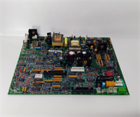
The GE H201TI (also known as the 1747-TB20) is a discrete output module designed for use in GE Fanuc’s Series 90-30 and 90-70 programmable logic controllers (PLCs). It provides 20 individual transistor (solid-state) outputs, allowing the PLC to control external devices such as solenoids, indicator lights, and small motors.Featuring a sink/common configuration, this module is typically used to switch DC loads to ground. It is a standard-sized module that can be installed in a DIN-rail mounted control panel or directly into a PLC chassis backplane. The H201TI is a reliable workhorse for discrete control applications requiring a high density of output points.
Installation & Configuration Guide
Preparation (10 min)
- Power Down: Turn off the main power supply to the control panel. Use a voltage tester to confirm no live circuits are present.
- Mounting Rail: Ensure the DIN rail or chassis is clean and free of debris. Verify the mounting holes align with the module.
- ESD Protection: If working in a dry environment, wear an anti-static wrist strap connected to a grounded point to prevent damage to the module’s electronics.
Removal (5–10 min)
- Cable Disconnection: Loosen the terminal screws on the front of the module. Carefully disconnect the wiring (output loads and power) to prevent strain on the solder joints.
- Release Latch: Press the release latch on the side of the module (if equipped) or gently pry it off the rail using a flat-head screwdriver.
- Storage: Place the removed module in an anti-static bag for storage or transport.
Installation (10 min)
- Align: Slide the module onto the DIN rail or into the chassis backplane. Ensure the connector pins engage securely.
- Lock: Press down firmly until you hear a distinct “click,” indicating the module is locked in place.
- Wiring: Connect the wires to the terminal block.
- Output 1-20: Connect the positive side of the DC load (e.g., solenoid or light) to these terminals.
- COM: Connect the common (negative) return path of the DC load to the COM terminal.
- L+/N: Connect the 24V DC power supply to the appropriate terminals.
Power-On & Test (10 min)
- Visual Check: Inspect the front panel for any physical damage or loose connections.
- Power Up: Restore power to the control panel.
- LED Indicators: Monitor the status LEDs:
- RUN/ALM: Green indicates normal operation; red indicates a fault (e.g., overvoltage or wiring error).
- Output LEDs: Blinking indicates the corresponding output is active.
- PLC Configuration: Verify the PLC recognizes the module on the network and that the output LEDs illuminate when the program sends a signal.
Troubleshooting Quick Reference
| Symptom | Probable Cause | Corrective Action |
|---|---|---|
| ALM Light ON | Overvoltage or wiring error | Check the 24V DC power supply voltage. Ensure no wires are touching adjacent terminals. |
| No Output | Open circuit in load | Check the continuity of the wiring to the load (e.g., solenoid coil). |
| Intermittent Output | Electrical noise | Use shielded cables and ensure the shield is grounded at both ends. Install ferrite chokes on the output wires. |
| Output Glitch | PLC scan time issue | Verify the PLC program is not cycling too fast for the load (e.g., a light flickering). |
Dimensions, Mounting & Wiring Notes
- Form Factor: DIN-rail mountable or chassis backplane (depends on the installation type)
- Dimensions: 120mm (Width) x 100mm (Height) x 75mm (Depth)
- Mounting: Secure the module to a 35mm DIN rail using the side clips or insert into a compatible PLC chassis.
- Wiring Notes: The output terminals are designed for 24V DC loads. Ensure the load current does not exceed the module’s rating (typically 0.5A per point, 1A total for common). The sink/common configuration means the load is switched to ground.
H201TI GE
FAQ
Can I use the H201TI to control AC loads?
No, the H201TI is a transistor (solid-state) output module designed for 24V DC loads only. To control AC loads (e.g., 120V AC solenoids), you would need a module with relay outputs, such as the GE H201RI (1747-RB20).Is this module hot-swappable?
No, the H201TI is not hot-swappable. You must power down the entire control system before removing or inserting this module to prevent damage to the PLC or the module itself.What is the difference between H201TI and H201RI?
The primary difference is the output type. The H201TI uses transistor outputs for DC loads, while the H201RI uses relay outputs, which can switch both AC and DC loads. The H201TI is for DC only, high-speed switching; the H201RI is for AC/DC, slower switching.Can I stack multiple H201TI modules in the same rack?
Yes, you can install multiple H201TI modules in a single PLC chassis as long as there is available slot space and the power supply can handle the total current load of all modules.What does the “TI” in H201TI stand for?
The “TI” typically stands for Transistor Input/Output. In this context, it refers to the solid-state (transistor) output technology used in the module.