 Tel:
Tel:  Email:
  WhatsApp:
 Description
Key Technical Specifications
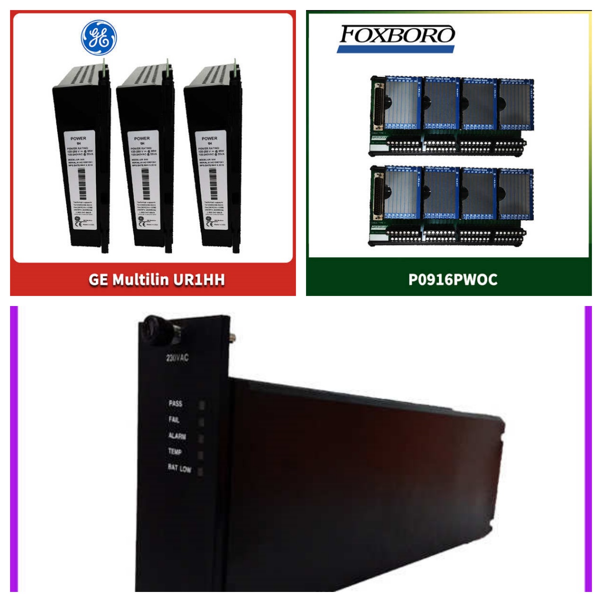
- Input Voltage (AC): 115 VAC or 230 VAC (configurable via transformer cable JTX1/JTX2)
- Input Voltage (DC): 125 VDC (Station Battery)
- Output Voltage: 125 VDC (distributed to VME racks and terminal boards)
- Power Conditioning: Integrated Control Power Filter (CPF) to reduce EMI noise
- Filter Module: Supports Corcom 30 A filter modules (typically 2 or 3 per rack)
- Diagnostic Interface: Connects to VCMI via J301 for data collection
- Relay Interface: Fused AC feeds (J17–20) connect to relay terminal boards
- Contact Input Voltage: 125 VDC excitation
- Application: Gas Turbine Control Management Systems (Speedtronic)
- Mounting: DIN Rail or Rack Mount within the Mark V/VI Control Cabinet
Product Introduction
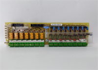
If you have ever stood in front of a roaring gas turbine control cabinet, you know that clean power is the difference between a smooth startup and a catastrophic nuisance trip. The GE DS2020PDMAG6 is the unsung hero of the Speedtronic Mark V and Mark VI systems. It isn’t just a simple power supply; it is a dedicated Power Distribution Module (PDM) designed to take the often “dirty” plant power (115/230 VAC or 125 VDC) and convert it into rock-solid 125 VDC for every single rack and terminal board in the system.The real value of the DS2020PDMAG6 lies in its built-in noise rejection. Industrial power grids are full of electromagnetic interference (EMI) from massive motors and switchgear. This PDM houses Control Power Filter (CPF) modules (often Corcom 30 A units) that strip out that electrical noise before it can reach the sensitive processor boards. I have seen turbines misbehave simply because a failing PDM let voltage ripple through to the logic cards. This module ensures the VCMI and I/O cores get the stable excitation voltage they need to keep the turbine spinning safely.
Quality SOP & Tech Pitfalls (The Reality Check)
The Lab Report (SOP):
We don’t just box these up and hope for the best. Here is the protocol we run on every DS2020PDMAG6:
- Visual & Counterfeit Check: We inspect the PCB for burn marks, swollen capacitors, and verify the GE part number labels match the board revision.
- Insulation Resistance Test: We use a megohmmeter to check the isolation between the high-voltage AC inputs and the low-voltage DC outputs to ensure no internal breakdowns.
- Live Load Test: We feed it 115 VAC and 125 VDC separately, verifying that the output stabilizes at a clean 125 VDC under load, with ripple well within OEM specs.
- Filter Integrity Check: We verify the internal fuses and the continuity of the EMI filter path.
- Anti-static Sealing: Once passed, it goes into a shielded anti-static bag with heavy-duty corner protection.
The Engineer’s Warning (Pitfalls):
The number one mistake I see during a PDM swap is ignoring the input configuration jumpers. This module can accept either 115 VAC or 230 VAC, but you must ensure the transformer cable is plugged into the correct jack (JTX1 or JTX2). If you feed 230 VAC into the 115 VAC setting, you will let the magic smoke out instantly. Also, when dealing with the 125 VDC station battery input, double-check your polarity. These cabinets have been rewired by electricians over decades, and trusting the wire color alone is a recipe for a blown fuse or a fried board.
Installation & Configuration Guide
Replacing a PDM is high-stakes because you are dealing with the cabinet’s main power. Follow this strictly:
- Pre-Installation: ⚠️ SHUT DOWN THE TURBINE. This is not a hot-swap module. Isolate the 125 VDC station battery breakers and the AC supply breakers feeding the cabinet. Verify zero voltage with a multimeter.
- Removal: Take a high-resolution photo of every single wire and connector on the old PDM. Label the JTX (transformer), DC input, and output cables. Unplug the connectors and unmount the module from the DIN rail or rack.
- Installation: Mount the new DS2020PDMAG6. Crucial Step: Before plugging anything in, verify the AC input voltage available at the cabinet terminals. Match the transformer cable to JTX1 (115V) or JTX2 (230V) exactly as the old unit was set. Reconnect all power and output cables using your photos as a guide.
- Power-On & Testing: Close the AC breaker first. Measure the output voltage at the distribution terminals to ensure you have a steady 125 VDC. If stable, close the DC battery breaker. Check the diagnostic link to the VCMI (via J301) to ensure the system recognizes the power status.
Compatible Replacement Models
- ✅ Drop-in Replacement: GE DS2020PDMAG6. This is the exact OEM part number. Ensure the physical revision matches your cabinet layout, as minor mechanical changes can happen over the years.
- ⚠️ Software/Firmware Compatible: GE Mark VI PDM variants. While newer Mark VIe systems use different distribution architectures, some PDM modules are cross-compatible within the Mark V/VI ecosystem. However, this usually requires a trained technician to verify the firmware handshake with the VCMI.
- ❌ Hardware Mod Required: Third-party universal power supplies. Do not attempt to wire a generic industrial DIN-rail power supply to replace this. The DS2020PDMAG6 has specific diagnostic communication lines (J301) and fused distribution paths that a generic supply cannot replicate, which will cause system faults.
Frequently Asked Questions (FAQ)
Can I hot-swap this PDM while the turbine is running?
Absolutely not. This module distributes the main logic power to the entire control cabinet. Removing it will cut power to the processors and I/O racks, causing an immediate turbine trip and potentially damaging the control system. The turbine must be shut down and secured.My cabinet has both AC and DC inputs. Which one does the PDM use?
The DS2020PDMAG6 is designed to handle both. Typically, the AC input is the primary source converted to DC, while the 125 VDC input acts as a redundant backup (often from the station battery) to ensure the control system stays alive if plant AC power is lost. The module uses diodes to manage this redundancy automatically.What does the J301 connector do?
J301 is the diagnostic data link. It connects the PDM to the VCMI (VME Communications Interface) board. This allows the turbine control software to monitor the health of the power supply, reporting issues like undervoltage or blown fuses directly to the operator’s HMI.I see “Corcom 30 A” mentioned. Do I need to buy that separately?
No, the Corcom 30 A filter modules are internal components housed within the PDM assembly or its associated CPF rack. They are part of the EMI noise reduction system. If you buy a complete DS2020PDMAG6 unit, these filters should already be installed.Why is the output voltage reading slightly higher than 125 VDC?
A slight variance is normal, especially if the system is running purely on the station battery (which can float higher when fully charged). However, if it is significantly out of range, check the regulation settings or the health of the internal AC/DC converter components. Consistently high voltage can damage downstream I/O boards.