 Tel:
Tel:  Email:
  WhatsApp:
 Description
Key Technical Specifications
| Parameter | Specification |
|---|---|
| Part Number | P0917YZ |
| Processor Type | 32-bit Industrial RISC |
| Memory (SDRAM) | 16 MB |
| Memory (Flash) | 32 MB |
| Communication | 100 Mbps Fiber/Copper Ethernet, Fieldbus |
| Device Support | Up to 32 FBMs (128 with FEM100) |
| Power Supply | 24V DC (Redundant Input) |
| Power Consumption | 8.5W (Max per module) |
| Operating Temp | 0°C to 60°C |
| Dimensions | 14.7 cm x 5.15 cm x 11.4 cm |
| Weight | 0.6 kg |
Product Introduction
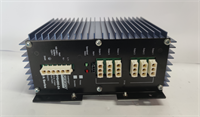
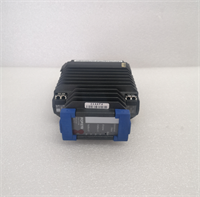
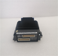
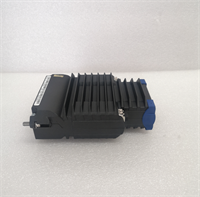
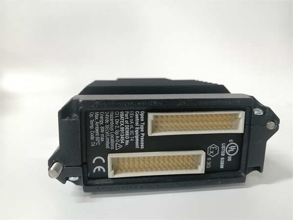
The Foxboro FCP270 P0917YZ is a high-performance Field Control Processor designed for the I/A Series Distributed Control System (DCS). It serves as the “brain” of the local control node, executing complex regulatory control, logic, and sequencing strategies. This module is specifically engineered to manage Field Bus Modules (FBMs), acting as the interface between the control network and physical field devices like sensors and valves.This unit distinguishes itself through its patented fault-tolerant architecture. It supports a “hot standby” redundancy configuration where two processors run in parallel; if the primary unit fails, the secondary takes over instantly without process interruption. The hardware features a robust cast aluminum enclosure rated for G3 environments, providing superior protection against dust, vibration, and electromagnetic interference common in oil & gas or chemical processing plants.
Installation & Configuration Guide
Phase 1: Preparation (10 min)
- Safety Protocol: Ensure the rack power is disconnected or the specific slot is depowered. Use Lockout/Tagout (LOTO).
- ESD Safety: Attach an anti-static wrist strap to the chassis ground.
- Inspection: Check the backplane connector on the carrier for bent pins. Verify the fiber optic or Ethernet ports are clean.
Phase 2: Removal of Old Unit (If applicable) (5–10 min)
- Label Cables: Tag communication cables (Port A/B) to ensure correct reconnection to the redundant pair.
- Disconnect: Unplug the 24V DC power connector and Ethernet/Fiber cables.
- Unlatch: Release the locking clip at the bottom of the module.
- Extract: Slide the module straight out. Do not rock it side-to-side to avoid damaging the backplane.
Phase 3: Installation (10 min)
- Insert Module: Align the FCP270 P0917YZ with the slot guides. Push firmly until the rear connector seats completely.
- Lock: Engage the locking tab until it clicks into place.
- Wiring: Reconnect the 24V DC power. Connect the Ethernet or Fiber optic cables to the appropriate ports.
- Redundancy Check: If installing a pair, ensure the inter-module sync cable (if required by your specific baseboard revision) is connected.
Phase 4: Power-On & Test (10 min)
- Energize: Apply 24V DC power.
- LED Verification: Check the front panel LEDs. “PWR” should be solid green. “RUN” indicates the processor is active.
- Software Handshake: Open the engineering workstation (e.g., Foxboro Evo or InTouch).
- Status Check: Confirm the processor reports “Primary” or “Secondary” status correctly and matches the hardware revision in the database.
Troubleshooting Quick Reference
| Symptom | Probable Cause | Corrective Action |
|---|---|---|
| No Power LED | Blown fuse or loose terminal | Measure voltage at the input connector. Check polarity. |
| Red Fault LED | Firmware mismatch or memory error | Cycle power. Re-download firmware/configuration from the engineering station. |
| Comms Timeout | IP Address conflict or cable cut | Ping the module IP. Inspect fiber optic cables for bends or breaks. |
| “Tracker” Mode Error | Redundancy sync failure | Check the partner module. Reseat both modules to ensure backplane contact. |
| Data Drift | Network noise or grounding | Verify shield grounding on communication cables. Check for EMI sources nearby. |
Dimensions, Mounting & Wiring Notes
- Dimensions: 14.7 cm (H) x 5.15 cm (W) x 11.4 cm (D).
- Mounting: DIN Rail or I/A Series specific carrier.
- Wiring Note: Use Shielded Twisted Pair (STP) for Ethernet connections. Keep communication cables separate from high-voltage AC lines to prevent signal corruption.
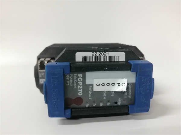
FCP270 P0917YZ FOXBORO
FAQ
What does the “G3” environmental rating mean?
G3 is a harsh environment classification. It means the FCP270 is tested to withstand severe levels of corrosion, dust, and electromagnetic interference. It’s built for the “dirty” side of the plant, not just climate-controlled server rooms.Can I use this module for standard PLC logic?
Yes, but it is optimized for process control. It supports IEC 61131-3 languages like Function Block Diagram (FBD) and Structured Text (ST), making it ideal for continuous process loops rather than just discrete machine logic.Why is my module stuck in “Tracker” mode?
In a redundant pair, one module is Primary and one is Tracker (Secondary). If yours is stuck as Tracker, the Primary might have failed, or the sync link between them is broken. Check the health of the partner module first.Does this support Fiber Optics?
Yes, the FCP270 typically supports connection to the control network via standard 100 Mbps fiber optics, which provides excellent noise immunity over long distances. Check the port type on your specific unit (RJ45 vs. SC/LC Fiber).How many Field Bus Modules (FBM) can this control?
Directly, it supports up to 32 FBMs. However, if you add a Fieldbus Expansion Module (FEM100), you can expand this capacity to control up to 128 FBMs.