 Tel:
Tel:  Email:
  WhatsApp:
 Description
Key Technical Specifications
| Parameter | Specification |
|---|---|
| Product Type | Foundation Fieldbus H1 Interface Module |
| Part Number | P0926GU (Current), P0926GW (Legacy) |
| Communication Protocol | Foundation Fieldbus H1, Ethernet/IP |
| Network Speed | 10 Mbps / 100 Mbps (Auto-sensing) |
| Channel Capacity | Up to 64 field devices per channel |
| Redundancy | Supported (Primary/Tracker configuration) |
| Connection Type | RJ-45 Ethernet, Terminal Block (Field side) |
| Power Input | 24 VDC (via Node Bus or separate supply) |
| Mounting | DIN Rail or Panel Mount (Carrier dependent) |
| Operating Temp | -20°C to +60°C |
| Certifications | CE, UL, CSA, FM Approved (Hazardous Locations) |
Product Introduction
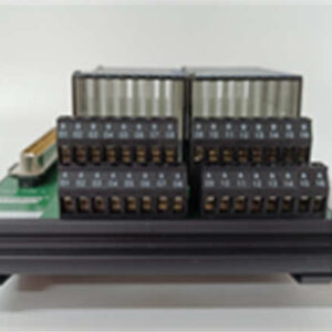
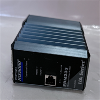
The Foxboro FBM233 is a Field Bus Module designed to bridge the gap between high-speed Ethernet networks and field-level instrumentation. It serves as a communication gateway in the I/A Series system, translating digital data from smart transmitters and valves into a format the main processor can utilize. This module is essential for integrating Foundation Fieldbus devices into your DCS architecture.This unit distinguishes itself with its ability to handle high-density device loads—managing up to 64 devices on a single link without significant latency. It features dual Ethernet ports for network redundancy, ensuring that a cable break doesn’t blind your control room. The ruggedized design handles the electrical noise typical of heavy industrial environments like refineries or pulp mills.
Installation & Configuration Guide
Phase 1: Preparation (10 min)
- Safety First: Lock out/Tag out (LOTO) the power supply to the carrier/rack. Even though it’s low voltage, shorting the backplane is bad news.
- ESD Protection: Wear your grounding strap. The internal comms chips are sensitive.
- Check Jumpers: Verify the termination switches or jumpers on the module if you are placing this at the end of a trunk line. (Default is usually unterminated).
Phase 2: Removal (Old Unit Only)
- Label Cables: Mark the Ethernet cables (Port A vs. Port B) and field wiring terminals.
- Unlock: Release the locking lever or unscrew the retention screws on the faceplate.
- Extract: Slide the FBM233 out of the carrier slot. Keep it flat; don’t let the connectors hang loose.
Phase 3: Installation (New Unit)
- Slot Alignment: Insert the module into the designated I/A Series carrier slot.
- Seat Connection: Push firmly until the rear connector mates with the backplane. You need a solid connection here.
- Secure: Engage the locking mechanism. If it’s a screw-lock type, don’t overtighten—snug is enough.
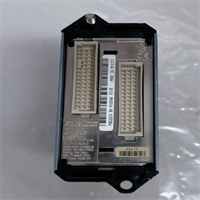
- Wire: Reconnect the twisted-pair field wiring to the terminal block. Ensure polarity (+/-) matches the diagram.
Phase 4: Power-On & Test
- Energize: Restore power to the rack.
- LED Check:
- COMMS: Should blink green (active traffic).
- STATUS: Solid green indicates healthy operation. Amber usually means “Out of Service” or configuration mode.
- System Scan: Open your engineering workstation (Foxboro Evo or I/A Series software). Force a scan to see if the module appears on the node bus.
Troubleshooting Quick Reference
| Symptom | Probable Cause | Corrective Action |
|---|---|---|
| STATUS LED is Red | Hardware failure or config error | Reseat the module. Check if the firmware version matches the node processor requirements. |
| No Communication | Backplane connection issue | Power down and reseat the card. Check the carrier slot fuses. |
| Intermittent Data | Loose field wiring | Tighten terminal block screws. Check for corrosion on the field bus cable shield. |
| Link Down | Ethernet cable fault | Swap the Ethernet cable. Try the secondary port if configured for redundancy. |
| Module Not Detected | Address conflict | Verify the physical address switches (if applicable) or software node assignment. |
Dimensions, Mounting & Wiring Notes
- Form Factor: Standard I/A Series FBM footprint (approx. 18mm width per slot).
- Mounting: Clips directly into the carrier rail; secured by a front latch.
- Connections:
- Field Side: Screw terminals for H1 Fieldbus (Twisted Pair).
- Network Side: Internal ribbon cable or direct backplane connection to the Node Bus.
- Termination: Remember to set the termination jumper if this is the last device on the segment. Unterminated lines cause signal reflection (ghosting).
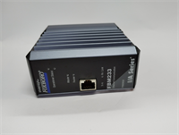
FBM233 FOXBORO
FAQ
1. What is the difference between FBM233 and FBM230?
The FBM230 is typically a discrete input/output module (digital signals). The FBM233 is specifically designed for Foundation Fieldbus communication, meaning it talks to smart instruments rather than simple on/off switches. They are not interchangeable.2. Can I use this with a non-Foxboro system?
Technically, it uses standard protocols, but the hardware interface (backplane) is proprietary to the Foxboro I/A Series carriers. You’d need a custom integration solution to make it work outside its native ecosystem.3. My FBM233 shows an amber light. Is it broken?
Not necessarily. Amber often means the module is powered but “Out of Service” (OOS) in the software configuration, or it hasn’t been assigned a node address yet. Check your control software status first.4. Does this support redundancy?
Yes. You can install two FBM233 modules to create a redundant pair (Primary and Tracker). If the primary fails, the tracker takes over the link management instantly.5. Where can I get the pinout diagram?
Check the Invensys/Foxboro documentation for “P0926GU Installation Sheet.” The terminal block is usually standard polarity, but always verify against the specific revision manual to avoid blowing the port fuse.