 Tel:
Tel:  Email:
  WhatsApp:
 Description
Key Technical Specifications
| Parameter | Specification |
|---|---|
| Signal Type | 4-20 mA Analog + HART Digital (FSK) |
| Channels | 8 Independent, Isolated Outputs |
| Resolution | 13-bit D/A Conversion |
| Accuracy | ±0.05% of Span |
| Load Impedance | 750 Ω (Max) |
| Supply Voltage | 24V DC (Field Powered or Sourced) |
| Isolation | 600 VAC (Channel-to-Ground/Logic) |
| Comms Speed | 1200 Baud (HART), 2 Mbps (Fieldbus) |
| Update Rate | ~60ms Settling Time |
Product Introduction
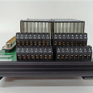
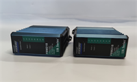
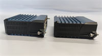
In the world of process control, “close enough” is a disaster waiting to happen. The FBM218 (P0922VW) is the module you use when you need to know exactly where that control valve is, not just where you hope it is. It’s an 8-channel analog output card, but unlike the dumb cards of the 90s, this one speaks HART. That means it pushes the standard 4-20mA signal to drive the process, but it also layers digital communication on top to ask the transmitter, “Hey, are you clogged? Is your temperature high?”I’ve seen these deployed in refineries where downtime costs thousands of dollars a minute. The redundancy capability here is the real selling point. You pair two of these modules (Master/Tracker configuration), and if the primary unit decides to quit, the backup takes over without bumping the process. It’s compact, it’s isolated, and frankly, it’s bulletproof—provided you don’t mess up the grounding.
Quality SOP & Tech Pitfalls (The Reality Check)
The Lab Report (SOP)
We don’t trust “New in Box” blindly anymore. Here is how we validate an FBM218:
- Visual Inspection: We check the DIN rail clips and the DB connector pins. Bent pins on the backplane are a death sentence.
- Continuity & Isolation: Using a Fluke 87V, we verify isolation between channels. A short between Channel 1 and 2 can backfeed voltage into a sensitive positioner.
- Live Loop Test: We hook it up to a test rack with a HART communicator (like a AMS Trex). We command 4mA, 12mA, and 20mA. We measure the actual current loop to ensure it’s within that ±0.05% spec.
- Digital Handshake: We verify the module can actually “talk” to a HART device. If the FSK modulation is dead, you have a very expensive analog card.
️ The Engineer’s Warning (Pitfalls)
Beware the “Ghost” Voltage. Because these modules have high channel-to-channel isolation (600Vac), they are susceptible to capacitive coupling if you run your signal cables next to high-voltage motor leads. I once spent six hours troubleshooting a “drifting valve” only to find the HART cable was bundled with 480V power lines. Separate your trays.Also, check your redundancy adapter. The FBM218 relies on a specific redundant adapter module (often P0916QD or similar interposer) to combine the outputs. If you swap the module but leave a corroded adapter in place, your redundancy is useless.
️ Installation & Configuration Guide
Phase 1: Pre-Installation
⚠️ Safety First: Even though it’s low voltage, you’re working near 24V DC power supplies that can arc. Turn off the segment power if possible.
- Photo Documentation: Take a picture of the wiring diagram or the existing terminal block.
- Check the Jumper: Some revisions have configuration jumpers for power sourcing. Verify the new unit matches the old unit’s jumper settings.
Phase 2: Removal
- Disconnect the field wiring harness (usually a screw-terminal assembly).
- Unlatch the module from the DIN rail or carrier.
- Pull the module straight out. If it’s part of a redundant pair, ensure you are pulling the correct one (Master vs. Tracker).
Phase 3: Installation
- Seat the Module: Slide the FBM218 onto the baseboard/DIN rail. Ensure the rear connector mates perfectly with the fieldbus interface.
- Redundancy Check: If installing in a pair, make sure the “Tracker” module is seated correctly relative to the “Master.”
- Wire It Up: Connect your 4-20mA loops. Keep the shield grounded at one end only (usually the chassis end) to avoid ground loops.
Phase 4: Power-On & Testing
- Apply 24V DC power.
- LED Check: The status LED should be Green. If it’s Red, you likely have a configuration mismatch or a bad backplane connection.
- Software Config: Go into your engineering workstation (Foxboro Evo or I/A Series). Download the database. The system will recognize the HART capabilities and allow you to view device variables.

FBM218 FOXBORO
Compatible Replacement Models
| Model | Compatibility Tier | Notes |
|---|---|---|
| FBM218 (P0922VW) | Exact Match | Standard revision. Most common. |
| FBM218 (Older Rev) | Drop-in Replacement | Earlier hardware revisions work but may lack firmware features. |
| FBM217 | Different Function | This is usually Analog Input. Do not confuse them. |
Frequently Asked Questions (FAQ)
Q: Can I mix standard 4-20mA devices and HART devices on the same card?
A: Yes. That’s the beauty of the FBM218. It treats every channel independently. You can have a dumb flow meter on Channel 1 and a smart positioner on Channel 2. The HART polling logic handles them individually.Q: My HART communication is failing, but the 4-20mA works fine. Why?
A: Usually, this is a load impedance issue or noise. HART requires a minimum loop resistance (usually 250Ω) to communicate digitally. If your loop resistance is too low, the analog current flows fine, but the digital FSK signal gets shorted out. Check your total loop resistance.Q: Does this module support “Burst Mode”?
A: No. According to the specs, the FBM218 supports Universal and Common Practice commands, but it does not support Burst Mode communication. If your device relies on bursting data continuously without being asked, you’ll need to reconfigure the device to “Poll-Response” mode.Q: What happens if the Master module fails?
A: The “Tracker” module detects the failure (via the internal heartbeat) and immediately assumes the Master role. The output current is maintained by the good module, so the valve shouldn’t move. It’s a seamless transfer—assuming you wired the redundancy adapter correctly.Q: Is the P0922VW obsolete?
A: It is effectively legacy hardware. While Schneider still supports the platform, you are mostly looking at surplus stock or refurbished units. If you are building a new system, look at the newer Compact I/O generations, but for a repair, this is the gold standard.