 Tel:
Tel:  Email:
  WhatsApp:
 Description
Product Deep Dive
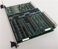
This ALSTOM C264MB1D69500130A300000C00N10 is a heavy-duty digital output module engineered specifically for the harsh electromagnetic and vibration environment of a GT13E2 gas turbine package. It acts as the final control stage, translating logic signals from the turbine governor into physical switch closures that drive solenoids, contactors, and alarm annunciators on the skid.What sets this board apart from generic PLC outputs is its ruggedized construction. The relays are Form A (SPST-NO) types rated for both 24V DC and 230V AC loads, which is critical for driving older legacy hardware found in turbine auxiliaries. In my experience troubleshooting these units, the gold-plated contacts and shock-absorbing mounting brackets are the key reasons these modules survive for decades in the field while standard industrial relays fail within months.
Key Technical Specifications
- Channel Count: 32 Digital Output Channels
- Output Type: Electromechanical Relay (Form A / SPST-NO)
- Load Rating: 24V DC / 230V AC (Resistive)
- Contact Material: Gold-plated (for low-level signal reliability)
- Isolation Voltage: 4 kV (High dielectric strength for turbine noise)
- Vibration Resistance: 2g RMS (Meets MIL-STD-810 for harsh environments)
- Mounting: DIN Rail or Screw Terminal
- Compatibility: Alstom GT13E2, GT13D, and related frame 6/7/9 variants
- Status Indicators: LED per channel (Visual feedback for troubleshooting)
- Operating Temp: -20°C to +70°C

Application & Pain Point Guide
The 2 A.M. Scram Scenario
Imagine this: It’s 2 A.M. at a combined heat and power plant. The control system detects a bearing temperature spike and sends a “Trip” signal. If this module’s relay sticks—even for a millisecond—the turbine doesn’t shut down. That’s the kind of failure this hardware is designed to prevent. It’s not just a switch; it’s the last line of defense against catastrophic mechanical damage.
- Gas Turbine Inlet Guide Vanes (IGV): Controls the servo actuators that modulate airflow. If a relay welds shut, the IGV freezes, causing a compressor stall.
- Fire & Gas Systems: Triggers the CO2 deluge or emergency venting. A failed-open relay here means the system can’t activate during a flare event.
- Lube Oil Pumps: Manages the “Run/Standby” sequence. In high-vibration zones, standard relays chatter; these don’t.
- Auxiliary Drives: Switches power to jacking oil pumps or turning gear motors during cooldown.
Field Note: The “Sticky Relay” Trap
I remember a site visit where a turbine kept tripping on “Loss of Flame” during startup. We replaced sensors, checked fuel pressure, everything. Turned out, it was this exact module. One relay was mechanically sticking due to a bent armature. The lesson? Always test the relay coil resistance. If it reads infinite, the coil is burnt; if it reads zero, the contacts are likely welded. Don’t just assume it’s a logic error in the PLC.