 Tel:
 Email:
 WhatsApp:
Description
Key Technical Specifications
| Parameter | Value |
|---|---|
| Product Model | DDC779BE02 |
| Order Number | 3BHE006805R0002 |
| Product Type | Signal processing and interface circuit board |
| Applicable Systems | ABB Symphony Plus, Advant OCS (verify per plant configuration) |
| Analog Inputs | 8 channels, 4–20 mA / 0–10 V DC |
| Digital Inputs | 16 channels, dry contact / wet contact |
| Digital Outputs | 8 channels, relay output |
| ADC Resolution | 24-bit |
| Analog Accuracy | ±0.1% FS |
| Signal Isolation | 2.5 kV AC |
| Supply Voltage | 24 V DC |
| Condition | New Original / New Surplus / Refurbished (Tested) |
Product Introduction
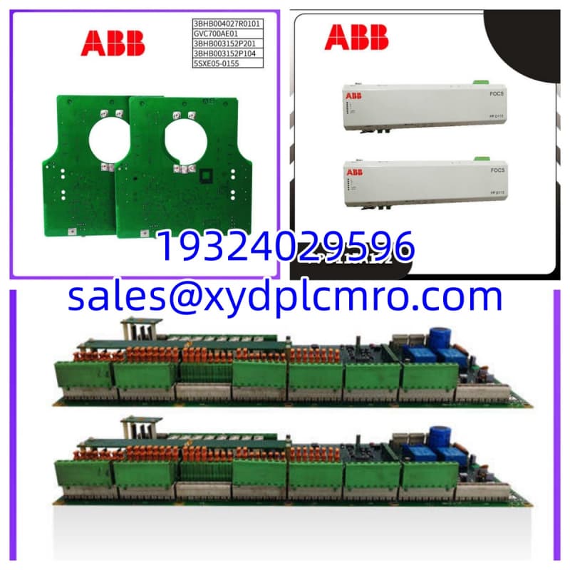
ABB DDC779BE02 3BHE006805R0002 is a signal processing and interface circuit board used in ABB Symphony Plus and Advant OCS control environments. It brings analog and digital field signals into the control system and provides relay outputs for local equipment control.This board is most useful when legacy I/O channels drift, relay outputs stick, or analog readings become noisy after years of plant operation. The 24-bit ADC and 2.5 kV isolation help reduce interference from motors, VFDs, and long cable runs. It is not a universal replacement for every ABB I/O card — the exact slot, backplane type, and firmware must match the existing configuration.
Installation & Configuration Guide
Preparation — 10 min
- Record system name, rack/slot position, and existing board serial number.
- Photograph all connectors, DIP switches, jumpers, and LED states.
- Confirm the replacement order number matches 3BHE006805R0002.
- Prepare ESD protection, insulated tools, and point-to-point wiring records.
Removal — 5–10 min
- Place affected loops in manual or safe state.
- De-energize the rack or isolate the module per plant procedure.
- Label every connector before removal.
- Remove the board without forcing terminal blocks or ribbon cables.
Installation — 10 min
- Inspect terminals for corrosion, burnt smell, or loose screws.
- Seat the board fully before reconnecting wiring.
- Verify DI/DO wiring polarity and relay load ratings.
- Confirm AI wiring uses shielded cable and proper grounding.
Power-On & Test — 10 min
- Measure 24 V DC supply before enabling the module.
- Power up the rack and check LED status indicators.
- Inject a known 4 mA and 20 mA signal into one AI channel.
- Verify DI status changes and DO relay operation.
- Return loops to automatic only after stable readings.
Troubleshooting Quick Reference
| Symptom | Most Likely Cause | First Check |
|---|---|---|
| No LEDs after power-up | Missing 24 V DC supply | Measure supply at module terminals |
| One AI channel reads high | Open loop or wiring fault | Check sensor loop and shield ground |
| All AI channels noisy | Ground loop or EMI | Separate signal wiring from power cables |
| DI channel stuck ON | Wet contact voltage leak | Measure input voltage with field device off |
| DO relay does not operate | Wrong wiring or failed relay | Check load voltage and relay feedback |
| Module faults after replacement | Wrong revision or configuration | Compare firmware, jumpers, and OEM manual |
Dimensions, Mounting & Wiring Notes
- Dimensions: Not confirmed from verified OEM data. Use the original board as a mechanical reference.
- Mounting: Installed in ABB control rack/slot; exact backplane type must match the existing system.
- Terminal Notes: Label every wire before removal. AI shields should be grounded at one end unless the OEM manual specifies otherwise.
- Wiring Notes: Keep 4–20 mA wiring away from VFD output cables. Relay loads must stay within rated contact limits.
FAQ
Can I replace an older DDC779 card with DDC779BE02?
Not automatically. The “BE02” suffix and 3BHE006805R0002 order number must match the existing configuration. Wrong revisions can change I/O mapping or firmware behavior.I see Profibus or Ethernet listed online. Does this board support them?
Some public listings mention Profibus DP or Ethernet, but those claims are not confirmed here. Treat communication features as unverified unless the physical board and OEM manual agree.Is this board still produced by ABB?
Many Advant OCS and Symphony Plus components are legacy items. Availability usually depends on surplus or tested stock rather than new factory production.Do you test these before shipping?
Function is verified under test conditions when tested stock is supplied. That includes visual inspection, supply voltage check, connector verification, and basic I/O confirmation. Full system integration testing depends on available infrastructure.What is the lead time?
Lead time depends on condition, quantity, and revision availability. Confirm per order.Can I use this in a high-EMI area?
The 2.5 kV isolation helps, but wiring practice still matters. Poor shielding or mixed cable trays can defeat even a well-designed board.What warranty do you offer?
12 months from shipment, covering functional defects under normal industrial use. Damage from incorrect wiring, overvoltage, or environmental exposure is not covered.