 Tel:
 Email:
 WhatsApp:
Description
Key Technical Specifications
| Parameter | Specification |
|---|---|
| Manufacturer | Yokogawa |
| Model | TDLS8000 |
| Measurement Principle | Tunable Diode Laser Absorption Spectroscopy (TDLAS) |
| Measured Components | O2, CO, CH4, CO2, H2O, NH3, H2S, HCl, CO+CO2, NH3+H2O and others depending on configuration |
| Measurement Range | Application-dependent; e.g., O2 up to 25%, CO up to 10,000 ppm, CH4 up to 5%, CO2 up to 50%, H2O up to 100% |
| Response Time | Typically seconds; exact value depends on application and configuration |
| Optical Path Length | Standard cross-duct path; extended path available for large ducts or stacks |
| Process Temperature | Suitable for high-temperature flue gas and process gas applications |
| Process Pressure | Suitable for near-atmospheric and moderate-pressure process conditions |
| Analog Output | 4–20 mA DC, configurable for concentration, transmission, process temperature or pressure |
| Digital Communication | HART and Modbus TCP / Ethernet |
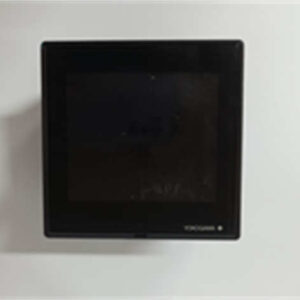
| HMI | 7.5-inch color touchscreen; supports multi-language display and trend monitoring |
| Power Supply | 24 V DC |
| Protection | IP66 / NEMA Type 4X enclosure protection |
| Hazardous Area | Zone 1/Div 1 and Zone 2/Div 2 versions available depending on certification |
| Self-Diagnostics | Laser status, detector signal, peak lock, transmission, temperature, memory and module health monitoring |
Product Introduction
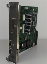
The TDLS8000 is built for applications where extractive sampling systems add too much lag, maintenance, or failure risk. Instead of pulling gas through filters, pumps and sample lines, it measures directly across the duct, stack or process line using a laser beam. That non-contact approach makes it especially useful in corrosive, dusty, high-temperature or high-moisture environments where conventional analyzers struggle.From an engineering standpoint, its strength is measurement stability under changing process conditions. The TruePeak absorption-area method reduces interference from background gas composition, pressure and temperature variation, which is critical when the analyzer is tied to combustion optimization or safety interlocks. The modular laser unit and sensor control unit also make field maintenance more practical, because the laser module can be replaced without full recalibration in many cases.
Quality SOP & Tech Pitfalls
The Lab Report (SOP)
- Visual and counterfeit check: Yokogawa nameplate, full model code, laser unit and SCU part numbers, revision labels.
- Mechanical inspection: flange interface, optical windows, purge fittings, cable glands, HMI condition.
- Power-up test: SCU initialization, laser status, detector signal, transmission level, HMI communication.
- Optical alignment check: verify beam transmission between laser unit and receiver/reflector side.
- Functional verification: analog output scaling, HART/Modbus communication, alarm and relay behavior.
- Documentation: record model suffix, gas configuration, software/firmware revision, serial numbers and test results.
The Engineer’s Warning (Pitfalls)
- Do not treat TDLS8000 as a generic gas analyzer. The measured component, range, optical path and hazardous-area certification are defined by the model suffix and factory configuration.
- Purge gas quality matters. Poor nitrogen or instrument air quality can foul optical windows, drift transmission readings, and create false low-signal alarms.
- Alignment is not optional. Even a robust in-situ analyzer will underperform if the optical path is misaligned, the windows are contaminated, or the flange mounting has shifted.
- For SIL-related applications, confirm whether the installed configuration is SIL2 or SIL3 capable and whether redundancy, voting logic or proof-testing procedures are required.
Installation & Configuration Guide
- Pre-Installation
- Confirm measured gas, range, optical path length and hazardous-area certification.
- Review flange type, duct diameter, process temperature and pressure limits.
- Verify purge gas supply, power supply and communication requirements.
- Photograph existing installation, nameplates, wiring and purge connections.
- Mechanical Installation
- Install flanges and ensure proper alignment between laser unit and receiver/reflector.
- Connect purge gas lines to optical windows and process windows as specified.
- Verify cable gland sealing and hazardous-area wiring practices.
- Electrical & Communication
- Connect 24 V DC power per OEM wiring diagram.
- Configure 4–20 mA outputs for the required measured variables.
- Enable HART or Modbus TCP communication as required by the control system.
- Commissioning
- Perform optical alignment and verify transmission levels.
- Confirm zero/span calibration or verification method.
- Validate alarms, diagnostics and response time against process requirements.
- Document final configuration, range scaling and maintenance intervals.
Compatible Replacement Models
| Compatibility | Model/Option | Notes |
|---|---|---|
| Drop-in | TDLS8000, same model suffix and gas configuration | Lowest risk; verify optical path, certification and revision |
| ️ Engineered Replacement | TDLS8000 with different suffix or range | Requires engineering review of calibration, communication and safety function |
| Not Recommended | Unrelated extractive analyzers or non-Yokogawa laser analyzers | Different measurement principle, interface and integration requirements |
Frequently Asked Questions (FAQ)
Q: What gases can the TDLS8000 measure?
A: It supports O2, CO, CH4, CO2, H2O, NH3, H2S, HCl and several multi-component configurations. The available range depends on the selected gas option and application.Q: Does it require a sample extraction system?
A: No. It is designed for in-situ measurement, so it typically eliminates sample probes, sample lines, pumps and conditioning systems.Q: Can it be used in hazardous areas?
A: Yes. Depending on configuration, it is available for Zone 1/Div 1 and Zone 2/Div 2 installations under applicable explosion-protection certifications.Q: Is it suitable for SIL applications?
A: It is designed and certified for SIL2 per IEC 61508, and SIL3 capability is available with dual-analyzer redundancy.Q: What causes low transmission alarms?
A: Common causes include window fouling, insufficient purge gas, misalignment, heavy dust loading, condensation or optical path obstruction.Q: Can the laser module be replaced in the field?
A: Yes. The laser module is designed for field replacement, but calibration, alignment and configuration must be verified after replacement.