 Tel:
Tel:  Email:
  WhatsApp:
 Description
Product Introduction
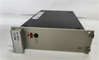
Let’s be honest, selecting spare parts for Safety Instrumented Systems (SIS) in high-risk industries like oil and gas or chemical processing leaves absolutely no room for error. This HIMA HIMatrix F3 AIO 8/401 is a compact analog I/O module specifically engineered by HIMA for high-reliability safety control scenarios. It integrates 8 analog input channels and 4 analog output channels, with the core task of precisely collecting critical field data—such as temperature, pressure, and liquid levels—and transmitting the signals to the main controller via a safety network. This ensures that Emergency Shutdown Systems (ESD) or Burner Management Systems (BMS) can respond correctly within milliseconds.For maintenance engineers, its real advantage lies in its high Safety Integrity Level (SIL 3) and outstanding environmental adaptability. The module features a rugged metal housing, and its electronic components are coated with protective lacquer, allowing it to operate stably in temperatures ranging from -20°C to +60°C. During our random warehouse inspections, we checked the module’s wiring terminals and communication interfaces—the build quality is incredibly solid, with absolutely no signs of oxidation or looseness. It integrates seamlessly into existing HIMatrix systems and can restore safety loop monitoring immediately upon power-up, helping you minimize the safety risks associated with unplanned downtime.
Key Technical Specifications
- Brand: HIMA
- Product Model: HIMatrix F3 AIO 8/401
- Series: HIMatrix Safety Control System
- Product Type: Safety-Related Analog I/O Module
- Input Channels: 8 Analog Inputs (AI)
- Output Channels: 4 Analog Outputs (AO)
- Safety Rating: Compliant with IEC 61508 SIL 3 standard
- Communication Interface: Integrated SafeEthernet interface
- Operating Temperature: -20°C to +60°C (Extended temperature range)
- Protective Design: Metal housing with protective lacquer on electronic components
Installation & Wiring Guide
Phase 1: Preparation (Estimated time: 15 minutes)
- Confirm that the safety control system rack is completely powered off, and strictly implement Lockout/Tagout (LOTO) procedures.
- Prepare a Phillips screwdriver, a multimeter, an anti-static wrist strap, and the Safety Designer configuration software (if recalibration is needed).
- Locate the wiring diagram, loop numbers, and previous system backups of the old module for reference.
Phase 2: Removing the Old Module (Estimated time: 10 minutes)
- ⚠️ Verify power is off: Use a multimeter to measure the backplane voltage and ensure there is no residual voltage before touching anything.
- Label and disconnect all analog signal wires and power cables from the old module one by one. Be gentle to avoid tearing any aged wire insulation.
- Take photos! Take photos! Take photos! Focus on the positions of the DIP switches, the MAC address label, and the exact wiring sequence of every single wire (this step will save you 90% of troubleshooting time later).
- Release the locking clips and pull the old module straight out.
Phase 3: Installing the New Module (Estimated time: 15 minutes)
- Put on your anti-static wrist strap and take the new HIMatrix F3 AIO 8/401 module out of its anti-static packaging.
- Compare it with the photos you just took and replicate the DIP switch and jumper settings from the old module one by one (Honestly, 9 out of 10 communication failures happen because this step wasn’t matched correctly).
- Align the new module with the rack guide rails, insert it smoothly and vertically, and lock the fixing clips once you hear the “click” sound.
- Restore all wiring according to your labels, and gently tug on them to confirm a secure connection. Pay attention to whether the shield layer is grounded at a single end as required.
Phase 4: Power-On Testing (Estimated time: 30 minutes)
- Before powering on, double-check all wiring for short circuits or misconnections, and confirm the power supply voltage matches the module’s nameplate requirements (typically 24V DC).
- Switch on the power and observe the module’s panel indicators. Under normal conditions, the RUN light should be solid or flashing regularly, and the ERR light should be off.
- Connect your programming laptop and check via SafeEthernet to see if the module is properly recognized by the controller. Verify the IP address and System ID.
- Perform an I/O signal simulation test (e.g., input 4-20mA using a signal generator) and confirm on the monitoring end that the values respond correctly with no safety alarms.
- If the indicators show an error (such as Open Circuit or Short Circuit), power off immediately and re-check the tightening torque of the wiring terminals and the continuity of the loop.