 Tel:
 Email:
 WhatsApp:
Description
Key Technical Specifications
| Parameter | Specification |
|---|---|
| Part Number | IS200TSVOH1BDC |
| Function | Servo I/O Terminal Board (TSVO) |
| System | GE Speedtronic Mark VIe |
| Paired Controller Board | IS200VSVOH1B (VME servo control board) |
| Servo Valve Outputs | 2 electro-hydraulic servo valve channels |
| LVDT/RVDT Inputs | Up to 6 LVDT position feedback inputs |
| Pulse-Rate Inputs | 2–14 kHz (flow/speed sensors) |
| External Trip Inputs | JD1 / JD2 connectors |
| Power | 24 VDC |
| Terminal Type | Barrier-type screw terminals (accept up to #12 AWG) |
| Redundancy Support | Simplex (JR1) and TMR fan-out (JR1/JS1/JT1) |
| Operating Temp | Typically 30°C to 50°C (confirm per OEM datasheet) |
| Mounting | VME rack, mounted below the VSVO board |
| Weight | Approx. 2 lbs (0.9 kg) |
Product Introduction
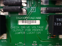
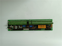
If you are replacing an IS200VSVOH1B servo board, you will almost certainly need to touch the TSVO terminal board sitting below it. The IS200TSVOH1BDC is that terminal board — the physical interface between the VSVO controller and the actual servo valves on the fuel or steam rack. It handles LVDT position feedback, servo current outputs, pulse-rate flow signals, and the external trip interface.In a TMR application, the TSVO fans out the LVDT and servo signals to three VSVO boards (R, S, T racks) through JR1, JS1, and JT1. In simplex, only JR1 is used. This is where wiring mistakes happen. I have seen technicians wire a simplex TSVO as if it were TMR, or vice versa, and then spend hours wondering why the servo loop will not initialize. The board itself is rugged — barrier terminals, shield termination strips, and a straightforward layout. But it is also unforgiving. A reversed LVDT lead or a loose shield wire will make a perfectly good VSVO board look faulty.
Quality SOP & Tech Pitfalls
The Lab Report (SOP)
Visual inspection first — label match (IS200TSVOH1BDC), no burnt smell, no corrosion on terminals, no cracked PCB around mounting holes. Check the barrier terminals for tightness and verify that shield termination strips are intact. Then it goes into a live Mark VIe test rack with a known-good IS200VSVOH1B. We verify 24 VDC at the board. We check LVDT excitation on the terminal block. We simulate an LVDT signal and confirm the VSVO reads a valid position. We verify the external trip inputs on JD1/JD2. We photograph the label and seal it in an anti-static bag.The Engineer’s Warning (Pitfalls)
Two mistakes cause unnecessary downtime. First, confusing TSVO (IS200TSVOH1B) with DSVO. TSVO uses barrier screw terminals; DSVO uses a different terminal style. They are not drop-in replacements for each other — the cabling and connector pinouts differ. Second, mixing up the simplex and TMR wiring. In TMR, the LVDT signals must fan out to all three VSVO boards through JR1, JS1, and JT1. In simplex, only JR1 is used. If you wire a simplex application with TMR jumpers or cables, the servo loop will either fail to initialize or report a sensor disagreement fault. I once watched a crew replace a TSVO during a forced outage, wire it for TMR on a simplex rack, and lose four hours chasing a “bad LVDT” alarm that was actually a wiring error.
Installation & Configuration Guide
- Pre-Installation ⚠️
Confirm the part number matches your existing board (IS200TSVOH1BDC). Photograph all terminal wiring, jumper positions, shield connections, and cable routing to the VSVO board. Verify whether your application is simplex or TMR. - Removal
Tag all LVDT, servo valve, pulse-rate, and trip wires at the terminal block. Disconnect the J5 cable from the VSVO board and the J1 cable from the VME rack. Unbolt the TSVO from the rack. Do not pull wires by the insulation. - Installation
Copy the wiring exactly. Mount the new TSVO in the same position below the VSVO board. Reconnect the J1 connector to the VME rack and the J5 cable to the VSVO front panel. Wire the LVDT, servo valve, pulse-rate, and trip circuits per the existing tags. Verify shield termination strips are connected to chassis ground. - Power-On & Testing
Apply 24 VDC. Verify the VSVO board boots without faults. Check LVDT position readings in the configuration tool (ToolboxST/ControlST). Verify servo valve response. Test the external trip input on JD1/JD2. If TMR, confirm all three VSVO boards report consistent LVDT values.
Compatible Replacement Models
| Compatibility | Model | Notes |
|---|---|---|
| ✅ Drop-in Replacement | IS200TSVOH1BDC | Same board, same revision family. Verify suffix matches. |
| ⚠️ Software/Config Check | IS200TSVOH1B (alternate suffix) | Same TSVO type but different suffix; verify terminal layout and jumper settings. |
| ⚠️ Alternative Terminal Style | IS200DSVOH1B | DSVO variant — different terminal type (cassette/box terminals). Not a direct drop-in without cabling changes. |
| ❌ Not Interchangeable | IS200VSVOH1B | This is the VME servo controller board, not the terminal board. Different function entirely. |
| ❌ Not Interchangeable | IS200TVIBH2BBB | Vibration terminal board — different application. |
Frequently Asked Questions (FAQ)
What is the difference between TSVO and VSVO?
The VSVO (IS200VSVOH1B) is the servo controller board that runs the control algorithm and sits in the VME rack. The TSVO (IS200TSVOH1B) is the terminal board mounted below it that connects to the field wiring — servo valves, LVDTs, and trip circuits. You need both.Can I substitute a DSVO for a TSVO?
No. DSVO boards use a different terminal style (cassette/box terminals vs. barrier screw terminals). The cabling and connector pinouts are not the same. Substituting one for the other requires rewiring and is not recommended during an emergency swap.Does this board work in TMR and simplex?
Yes. The TSVO supports both. In simplex, signals fan out through JR1 only. In TMR, signals fan out through JR1, JS1, and JT1 to three VSVO boards. The wiring must match your system configuration.What does the DC suffix mean?
The suffix letters in GE IS200 part numbers typically indicate revision, terminal style, or manufacturing variant. Always match the suffix to your existing board unless you have confirmed compatibility with GE documentation.How many LVDTs can it handle?
Up to 6 LVDT inputs. Each servo control loop can use 1, 2, 3, or 4 LVDTs for position feedback, depending on your configuration.Is this board obsolete?
The Mark VIe platform is still supported by GE Vernova, but individual board availability depends on stock and revision. Always confirm the exact part number and condition before purchasing.