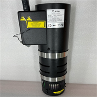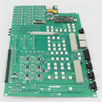
 Tel:
Tel:  Email:
  WhatsApp:
 Description
Key Technical Specifications
- System Architecture: ASYST R150 Indexer Platform
- Compatible P/N: 9700-4314-01 Rev. F, 9700-3800-02
- Operating Voltage: 24V DC Logic
- Axis Control: Multi-axis stepper/servo coordination
- Communication: Proprietary ASYST serial bus / RS-232
- Environmental Limit: Cleanroom Class 100 rated
- Mounting: Standard 19-inch rack or DIN rail
- Firmware: Proprietary ASYST Indexer OS
- Origin: USA / Japan Manufacturing
Product Introduction
Wafer transport jams in a fab don’t just stop a single tool; they bottleneck the entire production line. The ASYST INDEXER R150 acts as the central nervous system for these high-speed wafer handling operations, translating host commands into precise robotic arm trajectories. I’ve swapped out dozens of these in aging fabs, and when they fail, it usually means a burnt-out logic board or a fried motor driver.Engineers stick with this specific indexer because its mechanical-to-electrical integration is incredibly mature. It handles wafer mapping and handoff sequencing with deterministic timing that newer, generic controllers often struggle to match without extensive tuning. Just be aware that this specific Rev. F revision is notoriously picky about ground loops. Keep your signal grounds isolated from the chassis, or you’ll chase phantom communication errors for days.
Quality SOP & Tech Pitfalls (The Reality Check)
The Lab Report (SOP)
I don’t trust vintage boards blindly. Every R150 indexer goes through a strict bench test before it ships. First, we do a visual inspection under magnification to check for capacitor bulging or trace corrosion. Next, it goes on a live test rack where we verify the 24V DC logic and run a dummy wafer mapping cycle. We pull out the Fluke 115 to check insulation resistance on the motor outputs, log the exact firmware version, and finally seal it in an anti-static bag with a dated QC sticker.The Engineer’s Warning (Pitfalls)
Don’t just pull the old board and plug in the new one. The most common mistake I see is failing to copy the DIP switch and jumper settings from the old R150 module. I once watched a tech spend 14 hours troubleshooting a “faulty” replacement, only to realize he left the axis termination jumper open. Also, check your firmware revision. Mixing a Rev. E chassis with a Rev. F board without verifying parameter compatibility will cause handshake timeouts. Always photograph the old configuration before touching a screwdriver.
Installation & Configuration Guide
Phase 1: Pre-Installation (Safety & Documentation)
- ️ Lockout/Tagout: Kill the main 480V AC power to the indexer rack and wait 5 minutes for capacitors to discharge.
- Document Everything: Take high-resolution photos of the front panel DIP switches, jumper blocks, and all cable routing.
- ESD Prep: Ground yourself. Semiconductor boards are highly sensitive to static discharge.
Phase 2: Removal
- Label Wires: Tag every connector with masking tape and a marker. Do not rely on memory.
- Disconnect: Unplug the ribbon cables and power harnesses gently. Never pull by the wires.
- Extract: Release the DIN clips or remove the rack mounting screws, then slide the old module out.
Phase 3: Installation
- Copy Settings: CRITICAL: Transfer every DIP switch and jumper to the exact position shown in your Phase 1 photos. This prevents 90% of startup failures.
- Seat the Module: Slide the new ASYST INDEXER R150 into the slot. Ensure the backplane connector seats fully without forcing it.
- Reconnect: Plug in the cables according to your labels. Double-check that ribbon cables are oriented correctly.
Phase 4: Power-On & Testing
- Pre-Power Check: Verify no loose screws or wire strands are shorting the backplane.
- Apply Power: Turn on the 24V DC logic first, then the main power. Watch the LED boot sequence.
- Verify: Check for solid green status LEDs. Download the machine recipe and run a dry-cycle mapping test before loading real wafers.
Compatible Replacement Models
| Compatibility Tier | Model / Action | Notes |
|---|---|---|
| Drop-in Replacement | ASYST R150 9700-4314-01 Rev. F | Direct hardware match. Verify jumper settings. |
| ️ Software Compatible | ASYST R150 9700-3800-02 | Same hardware family. May require firmware flash or parameter reload (~2 hrs labor). |
| Hardware Mod Required | ASYST R200 Series | Different backplane and footprint. Do not use unless doing a full system upgrade. |
Frequently Asked Questions (FAQ)
Can I hot-swap this indexer module while the rack is powered on?
Absolutely not. The ASYST R150 backplane is not designed for live insertion. Hot-swapping will likely fry the new board’s logic circuits and potentially damage the backplane. Always follow proper Lockout/Tagout procedures.My old board has a different revision letter. Will this Rev. F still work?
Usually, yes, but it’s not guaranteed. ASYST made minor updates between Rev. E and Rev. F. The hardware is physically identical, but you must copy the old jumper settings exactly. If the system throws a communication fault after installation, the firmware parameters likely need to be reloaded via the service terminal.Does this come with the original ASYST service manuals?
No. ASYST was acquired by MKS Instruments years ago, and legacy documentation is hard to find. We provide basic wiring and DIP switch guides based on field experience. For deep-level software troubleshooting, you’ll need to contact MKS support or check third-party archival sites.How do I know if the board is actually new and not refurbished?
We sell these strictly as New Surplus. They are factory-sealed, never powered on in a production environment, and come with our 1-year functional warranty. If you open the box and see fingerprints or scratched mounting holes, reject it immediately.What is the most common cause of failure for these indexers?
In my experience, it’s usually not the board itself. It’s contaminated ribbon cables or oxidized backplane pins causing intermittent signal loss. Before you blame the new R150 module, clean the backplane connectors with electronic contact cleaner and inspect the ribbon cables for micro-fractures.Can I use standard industrial 24V power supplies for this?
You can, but make sure they are low-noise, regulated supplies. Cheap switching power supplies introduce ripple that can cause the indexer’s analog sensor circuits to misread wafer positions. Stick to reputable brands like Mean Well or TDK-Lambda.