 Tel:
Tel:  Email:
  WhatsApp:
 Description
Key Technical Specifications
| Parameter | Specification |
|---|---|
| Input Voltage | 115 / 230 V AC (Auto-ranging) |
| Output Voltage | 24 V DC (Adjustable via trim pot) |
| Output Current | 10 A (Continuous) |
| Peak Current | 20 A (Short duration) |
| Efficiency | > 90% (Typical load) |
| Holding Time | > 20 ms at full load (Buffer capacity) |
| Parallel Operation | Yes (Active Load Sharing / Diode OR-ing) |
| Signaling | OK Signal Relay (Potential-free contact) |
| Mounting | Top-Hat Rail (DIN 35mm) |
| Dimensions | Approx. 125 x 125 x 125 mm (Varies by heatsink) |
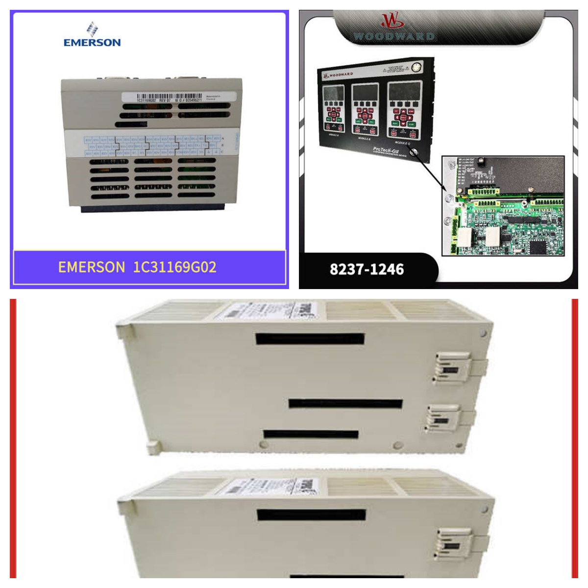
Product Introduction
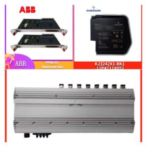
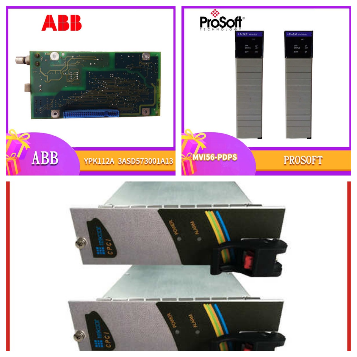
If you’ve ever stared down a tripped PLC during a startup because the power supply couldn’t handle the inrush current of a valve bank closing simultaneously, you know why we use the PVD164A01R1066. This isn’t your standard off-the-shelf switching power supply; it’s built specifically for the harsh electrical environment of ABB’s AC 800M systems.I’ve deployed these units in paper mills where the voltage sags are notorious. The PVD164 series is distinct because of its robust holding time—it can bridge those nasty 10-15ms brownouts that would brick a cheaper unit. The “10” in the spec usually denotes the 10 Amp continuous rating, which is plenty for a mid-sized controller rack but leaves enough headroom for future expansion. It’s heavy, metal-cased, and frankly, boring—which is exactly what you want in a power supply. Boring means reliable.
Quality SOP & Tech Pitfalls (The Reality Check)
We treat power supplies with suspicion until proven otherwise. Capacitors degrade, and fans seize.The Lab Report (SOP):
- Visual Inspection: We check the terminal blocks for heat discoloration (a sign of loose screws) and the PCB for bulging capacitors.
- Load Bank Test: We hook it up to a resistive load bank and ramp it to 8A. We verify the voltage stays within the 24V ±2% tolerance.
- Ripple Check: Using an oscilloscope, we check for excessive AC ripple on the DC output. High ripple kills sensitive transmitter cards.
- Signal Verification: We simulate a fault to ensure the “OK” relay drops out correctly, triggering the alarm in the DCS.
The Engineer’s Warning (Pitfalls):
The biggest mistake I see is ignoring the parallel mode jumper/settings. If you install two of these side-by-side for redundancy (which you should), they need to be configured to share the load. If you don’t set the master/slave or active sharing mode correctly, one unit will do all the work, run hot, and die prematurely while the backup sits idle. Also, never ignore the “DC OK” wiring—it’s your early warning system for a failing PSU.
Installation & Configuration Guide
Swapping this unit is straightforward, but rushing leads to sparks.
- Pre-Installation:
- ⚠️ CRITICAL: Lockout/Tagout (LOTO) the main AC input. Even though the terminals are covered, 230V AC has a way of finding you.
- Discharge the bus. Wait at least 2 minutes after power removal for internal capacitors to drain.
- Removal:
- Remove the terminal cover.
- Label your wires—specifically the DC output polarity and the Signal (Sig) wires.
- Unclip the module from the DIN rail. These units are heavy; support the bottom so you don’t bend the rail.
- Installation:
- Clip the new PVD164A01R1066 onto the rail.
- Reconnect wires. Torque the terminals. Do not guess. Loose connections cause heat; heat causes fires.
- Set the voltage trimmer. Measure at the terminals, not just the display.
- Power-On & Testing:
- Apply AC power. Listen for the relay click.
- Verify the green LED illuminates.
- Check the redundant alarm circuit (if wired) to ensure the panel doesn’t falsely report a failure.
Compatible Replacement Models
| Compatibility Tier | Part Number | Notes |
|---|---|---|
| ✅ Direct Replacement | PVD164A01 | The base model. Ensure the suffix (R1066) matches your specific redundancy requirements. |
| ✅ Functional Match | PVD164A01R1065 | Very similar revision. Usually interchangeable, but double-check the datasheet for slight efficiency curve differences. |
| ⚠️ Software/Config | PVD164Bxx | Newer generation. Physically fits, but may have different communication protocols or dip switch logic. Requires manual verification. |
| ❌ Incompatible | CP-E Series | Completely different form factor and mounting. Do not attempt to retrofit without changing the cabinet layout. |
Frequently Asked Questions (FAQ)
Q: Can I mix this with older ABB power supplies in the same rack?
A: Generally, no. Mixing different generations on the same DC bus can lead to uneven load sharing. The newer unit might try to compensate for the older, drooping unit, causing it to overheat. Stick to matched pairs.Q: What does the “R1066” suffix actually mean?
A: Suffixes in ABB land usually denote specific customer configurations or regional certifications (like marine approval). For standard industrial use, the core functionality remains 24V/10A, but always check the label for “Marine” or ” hazardous area” restrictions if you are in a strict zone.Q: My “DC OK” light is blinking. Is it dying?
A: Not necessarily. It could be thermal protection kicking in. Check the ambient temperature inside the cabinet. If it’s over 50°C, the unit might be derating itself. Clean the filters and check the airflow before condemning the module.Q: Does this support hot-swapping?
A: Yes, the chassis supports it, but only if you have the diode modules installed correctly for isolation. If you just rip it out without checking the backplane architecture, you risk dropping the whole rack. Proceed with caution.Q: How long is the shelf life on these?
A: The electrolytic capacitors inside have a shelf life. If you buy “New Surplus” that was manufactured 10 years ago, the capacitors might have dried out. We “reform” the capacitors by slowly ramping up the voltage before shipping to prevent immediate failure upon installation.