 Tel:
Tel:  Email:
  WhatsApp:
 Description
Key Technical Specifications (For Spare Parts Verification)
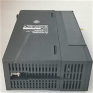
- Product Model: A1S65B-S1
- Manufacturer: Mitsubishi Electric
- System Platform: MELSEC A-Series (specifically A1S family)
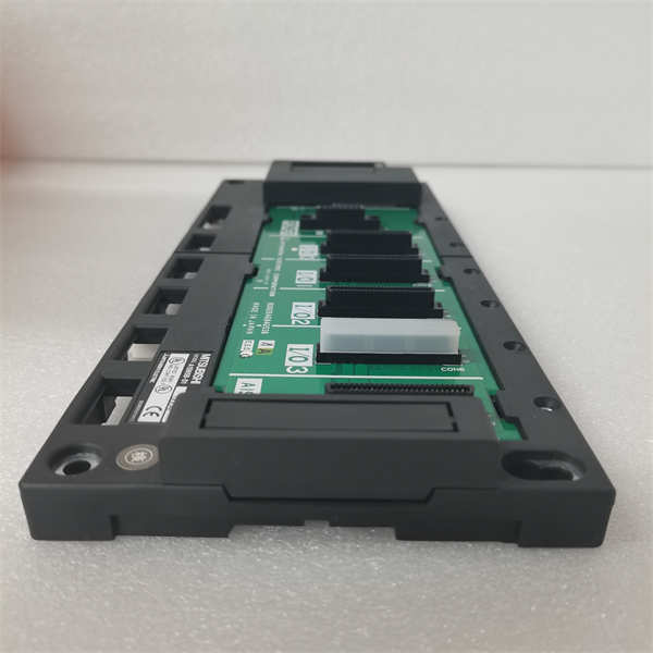
- Slot Configuration: 5 slots total (Slot 0 reserved for CPU, Slots 1–4 for I/O or special function modules)
- Power Supply Input: Requires external A1S62P or A1S63P power supply module installed in dedicated slot
- Backplane Bus: Proprietary parallel bus for communication between CPU and I/O modules
- Mounting: DIN rail or panel mount (with optional brackets)
- Dimensions: Approx. 270 mm (W) × 90 mm (H) × 90 mm (D)
- Connector Type: Edge connectors for module insertion; screw terminals for power supply interface
- Compatibility: Only accepts A1S-series modules (e.g., A1SCPU, A1SX40, A1SY80); not compatible with Q-series or newer platforms
- Diagnostic Indicators: None on base unit itself; status derived from CPU and module LEDs
System Role and Impact of Failure
The Mitsubishi A1S65B-S1 is the physical and electrical backbone of the A1S PLC system, commonly deployed in automotive assembly lines, packaging machinery, and legacy process skids from the 1990s through early 2000s. It houses the CPU and up to four I/O or specialty modules (e.g., analog, high-speed counter, communication). Without a functional base unit, the entire PLC station becomes inoperable.
Failure of the A1S65B-S1—though rare due to its passive design—typically stems from mechanical damage, corrosion, or internal trace fractures. Such a failure disrupts power delivery or backplane communication, causing the CPU to fault or I/O modules to go offline. In a production environment, this results in immediate machine stoppage. Because the A1S platform lacks built-in redundancy in most installations, there is no failover path, making the base unit a single point of failure for the entire control cell.
Reliability Analysis and Common Failure Modes
As a primarily passive component, the A1S65B-S1 has no active electronics, which contributes to its long service life. However, after decades of operation, several failure mechanisms emerge:
- Backplane connector wear: Repeated module insertion/removal causes edge contact fatigue, leading to intermittent signal loss or high resistance.
- PCB delamination or trace cracking: Thermal cycling and mechanical stress (e.g., from nearby motor vibration) can fracture thin copper traces, especially near mounting points or power terminals.
- Terminal block corrosion: Moisture or chemical exposure in harsh environments oxidizes power input screws, increasing resistance and causing voltage drop to modules.
- Physical damage: Dropping during maintenance or overtightening of DIN rail clamps can crack the housing or internal structure.
A key vulnerability is its dependency on precise mechanical alignment—bent pins or warped chassis prevent proper module seating, triggering “module not recognized” errors.
Recommended preventive actions:
- Avoid unnecessary module swapping; handle base unit with care during maintenance
- Inspect DIN rail mounting for stability and corrosion
- Verify tightness of power supply terminal screws during routine checks
- Use anti-static precautions when handling to prevent latent ESD damage to mating surfaces
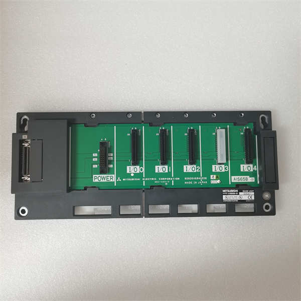
A1S65B-S1 MITSUBISHI
Lifecycle Status and Migration Strategy
Mitsubishi Electric officially discontinued the A1S series, including the A1S65B-S1, and shifted focus to the Q-series and now iQ-R/iQ-F platforms. No new base units are available, and factory repair services have been terminated. Continuing to operate with this hardware relies entirely on secondary market availability, which is dwindling and carries no performance guarantee.
Short-term mitigation includes:
- Securing one or more tested spare base units for critical cells
- Standardizing on common rack configurations to maximize interchangeability
- Avoiding modifications that stress the chassis (e.g., forced wiring strain)
For long-term sustainability, Mitsubishi’s recommended migration path is upgrading to the MELSEC iQ-R or iQ-F series. While there is no direct replacement, the R161BUD (for iQ-R) or FX5-485-BD-based racks (for iQ-F) offer modern alternatives. Migration requires:
- Replacement of the entire PLC station (CPU, base, I/O modules)
- Rewiring of field connections (though existing cable ducts can be reused)
- Full reprogramming in GX Works3 (for iQ-R) or GX Works2 (for iQ-F)
- Retesting of all logic, timing, and safety interlocks
Given the age of A1S systems, a phased approach—starting with the most failure-prone or production-critical lines—is advisable. This preserves operational continuity while systematically retiring obsolete infrastructure and restoring access to technical support, cybersecurity updates, and future expansion capability.