Key Technical Specifications
- Part Number: HIEE200038R0001
- Manufacturer: ABB
- Product Type: I/O Module / Relay Interface Board
- Input Voltage: 24V DC
- Output Voltage: 5V DC
- Output Current: 1A
- Operating Temperature: -40°C to +85°C
- Protection Rating: IP20
- Dimensions: 90mm × 60mm × 30mm
- Weight: Approximately 0.84 kg
- Communication: Modbus TCP/IP, RS-485
- Mounting: DIN rail or panel mount
- Indicators: LED indicators for power, signal, and relay status
- Configuration: Jumper-configurable for application-specific settings
Product Introduction
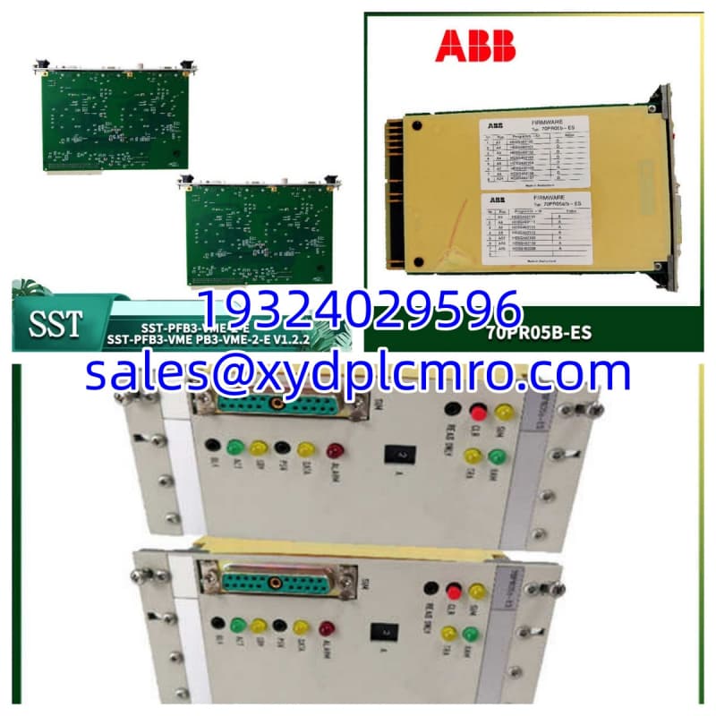
The ABB HIEE200038R0001 is an I/O module from ABB’s industrial automation module series, functioning as a relay interface board that converts digital signals into relay contact actions for external device control. It accepts 24V DC input, provides 5V DC / 1A output, and supports Modbus TCP/IP and RS-485 communication protocols for integration with DCS, PLC, and SCADA systems.This module targets process control environments — chemical plants, oil and gas facilities, power generation, and building automation — where reliable signal isolation and protocol bridging are required. The -40°C to +85°C operating range indicates industrial-grade environmental tolerance. As a discontinued part, available units come from surplus channels, making pre-purchase verification of condition and test documentation essential.
Installation & Configuration Guide
Phase 1: Preparation (10 min)
- De-energize the 24V DC supply feeding the module and apply lockout/tagout.
- Verify 0V at the input terminals with a multimeter before proceeding.
- Gather ESD protection (wrist strap, mat), small flathead screwdriver, and the replacement module.
- Photograph the existing module’s jumper positions, DIP switch settings, and all wiring connections.
- Confirm the replacement HIEE200038R0001 matches the removed unit’s revision markings.
Phase 2: Removal (5–10 min)
- Disconnect all field wiring: 24V DC input, output terminals, communication cables (RS-485 or Ethernet), and any relay output connections.
- Label each wire if not already labeled.
- Release the module from the DIN rail or remove panel mounting screws.
- Inspect terminal blocks for corrosion, discoloration, or loose contacts.
Phase 3: Installation (10 min)
- Set all jumpers on the replacement module to match your photo record from Phase 1.
- Mount the module on the DIN rail or panel using original hardware.
- Reconnect all wiring in reverse order of removal — 24V DC input first, then outputs, then communication.
- Verify terminal tightness. Loose 24V connections cause intermittent relay chatter.
Phase 4: Power-On & Test (10 min)
- Restore 24V DC power.
- Observe LED indicators — confirm power LED illuminates, no fault LEDs active.
- Verify Modbus TCP/IP or RS-485 communication handshake with the host controller.
- Trigger a test digital input and confirm the corresponding relay contact actuates.
- Monitor for 10 minutes under normal operating conditions, checking for abnormal heat at the output stage.
Troubleshooting Quick Reference
| Symptom | Likely Cause | First Check |
|---|---|---|
| No power LED | 24V DC supply fault or wiring error | Measure voltage at module input terminals — confirm 24V DC ±10% |
| Relay does not actuate | Jumper misconfiguration or input signal missing | Verify jumper settings match system config; measure input signal presence |
| No communication | RS-485 wiring reversed or Modbus address mismatch | Check A/B lead polarity on RS-485; verify node address jumpers |
| Intermittent relay chatter | Loose 24V input connection | Tighten all input terminals; check for corroded contacts |
| Module overheats | Output short circuit or excessive load | Disconnect output load; measure output current — confirm ≤1A |
| LEDs show fault state | Internal failure or firmware issue | Power cycle; if fault persists, replace module |
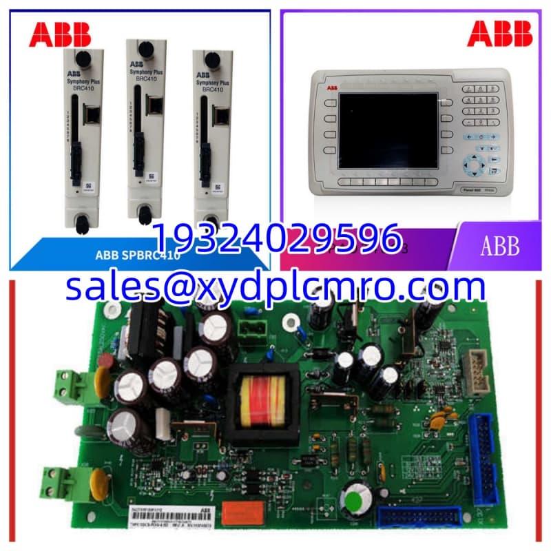
Dimensions, Mounting & Wiring Notes
- Dimensions: 90mm × 60mm × 30mm (H × W × D)
- Weight: Approximately 0.84 kg
- Mounting: DIN rail clip or panel mount via screw holes
- Wiring: 24V DC input terminals, 5V DC output terminals, RS-485 A/B terminals, and Ethernet port (if Modbus TCP/IP is used). Always reference the ABB wiring diagram for your specific system configuration — do not assume terminal assignments across different installations.
FAQ
What exactly does this module do in a control system?
It acts as a signal bridge — taking digital commands from a PLC or DCS and converting them into physical relay contact closures that switch external equipment (valves, contactors, indicators, etc.). The Modbus TCP/IP and RS-485 interfaces let the host system monitor relay status and send commands over the network.Can I use this module with any PLC brand?
The relay output side is brand-agnostic — any PLC can drive a relay contact. The Modbus TCP/IP and RS-485 communication side requires the host controller to support those protocols. Most major PLC platforms (Siemens, Allen-Bradley, Schneider, ABB AC800, etc.) support Modbus, but verify your specific controller’s Modbus implementation before relying on it.I’m seeing the relay click but the downstream device doesn’t respond — what’s wrong?
Check the relay contact rating against your load. The module outputs 5V DC / 1A — if your downstream device requires higher voltage or current, the relay contacts may not be sufficient. Also verify the external device’s power supply is active independently.Is this the same as a standard relay output card?
Not exactly. A standard relay output card just provides isolated relay contacts. The HIEE200038R0001 adds communication capability (Modbus TCP/IP, RS-485) and configurable jumper settings, making it more of an intelligent interface module than a simple relay card.How do I know if a surplus unit is trustworthy?
Ask the supplier for a test report covering: power-on self-test, relay actuation verification, communication handshake test, and output voltage/current measurement under load. Units sold without any test documentation carry higher risk — especially for a part in the -40°C to +85°C temperature class, which suggests it may have seen harsh service environments.What’s the lead time if it’s not in stock?
As a discontinued ABB module, availability depends entirely on surplus market conditions. Lead times can range from days to months. If this module controls a safety-adjacent or production-critical function, securing a spare now is the prudent move.