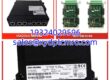
Key Technical Specifications
- Product Model: PM33211BP-5-1-3-F
- Manufacturer: Pioneer Magnetics
- Product Type: High Voltage Switching Power Supply
- PWM Controller: UC3843 (8-pin)
- PFC Controller: FA5331
- PFC DC Bus Voltage: ~380 VDC
- Protection Features: Over-voltage, Over-current, Short-circuit
- Topology: AC/DC with Active PFC
- Mounting Style: Internal Chassis / Rack Mount
- Operating Environment: Industrial, Low Noise / EMC Compliant
- Common Failure Points: Start-up Resistor, FA5331 V0 Pin Solder Joint
Product Introduction
Pioneer PM33211BP-5-1-3-F is a high voltage switching power supply module designed for industrial automation and specialized electronic equipment. It converts incoming AC power to a regulated high voltage DC output using an active Power Factor Correction (PFC) stage followed by a PWM-controlled DC/DC converter.This module relies on the UC3843 PWM controller and FA5331 PFC controller to maintain stable output under varying loads. Field technicians frequently encounter a specific failure where the FA5331 V0 pin develops a cold solder joint, causing the PFC stage to fail and leaving the filter capacitor without the expected 380V DC bus voltage. The PM33211BP-5-1-3-F includes built-in over-voltage and over-current protection to safeguard downstream sensitive equipment during fault conditions.

Installation & Configuration Guide
Preparation (10 min)
Verify the replacement unit matches the exact part number PM33211BP-5-1-3-F. Gather insulated tools, a multimeter rated for high voltage, and an ESD wrist strap. (I once saw a tech use a standard multimeter on a PFC bus and blow the input fuse—always use properly rated test equipment.) Ensure the system is completely de-energized and capacitors are discharged before proceeding.Removal (5–10 min)
Document all wire connections with photos before disconnecting. Remove mounting screws and carefully extract the module. Inspect the backplane or chassis connectors for signs of arcing, corrosion, or thermal damage. Check the mating connector for bent or pushed-back pins.Installation (10 min)
Align the PM33211BP-5-1-3-F with the mounting points and secure all fasteners to specified torque. Reconnect all wiring exactly as documented. Double-check that no wires are pinched or routed near sharp edges. Verify that the PFC and PWM sections have adequate airflow clearance.Power-On & Test (10 min)
Restore AC power and immediately measure the PFC bus voltage at the filter capacitor. It should read approximately 380V DC. If absent, check the FA5331 Vstart/control pin for proper logic level. Measure the final output voltage against specifications. Monitor for abnormal noise or heating during the first 15 minutes of operation.
Troubleshooting Quick Reference
| Symptom | Probable Cause | Action |
|---|---|---|
| No Output Voltage | Start-up resistor open or UC3843 failure | Measure VC pin; replace start-up resistor |
| PFC Bus Low / Absent | FA5331 V0 pin cold solder joint | Resolder V0 pin to PCB pad |
| Intermittent Shutdown | Over-current protection tripping | Check downstream load for shorts |
| Excessive Noise | Filter capacitor degradation | Measure ripple voltage; replace cap |
| UC3843 Not Starting | VR pin pulled to 0V externally | Disconnect external circuit; verify VR = 5V |
| Repeated Fuse Blow | Bridge rectifier or switch tube shorted | Test all semiconductors before replacing fuse |
Dimensions, Mounting & Wiring Notes
- Form Factor: Internal module power supply
- Mounting: Chassis mount with mechanical fasteners
- Cooling: Requires adequate airflow; do not obstruct ventilation
- Wiring: Use high-voltage rated conductors; maintain proper creepage and clearance distances
- Safety: High voltage present on PFC bus (380V DC) even when primary AC is disconnected. Always verify zero energy before servicing.

Quality Assurance & Testing Protocol
Incoming Inspection
We verify the origin of every PM33211BP-5-1-3-F against manufacturer lot records. Anti-counterfeit checks include visual inspection of PCB silkscreen, component date codes, and solder quality. Physical inspection confirms no cracked transformers, bulging capacitors, or burned components. All connectors and terminals are verified intact.Live Functional Testing
Each unit is tested on a dedicated high voltage test bench. We perform a power-on self-test and verify PFC bus voltage reaches 380V DC nominal. Output voltage regulation is tested across the full load range. Protection circuits are validated by simulating over-current and over-voltage conditions. A 24-hour load test confirms thermal stability. A test report is generated for every unit.Electrical Testing
Insulation resistance is verified between primary and secondary at 500V DC. Ground continuity is confirmed between chassis and earth terminal. Hi-pot testing is performed per applicable safety standards. Output ripple and noise are measured under full load.Firmware / Component Verification
We document the UC3843 and FA5331 controller part numbers. All DIP switches, jumpers, and trim potentiometer positions are photographed before testing. This ensures you receive exactly what you ordered.Final QC & Packaging
A QC signature validates the test report. The module is sealed in anti-static shielding with high voltage warning labels. Bubble wrap and a rigid carton protect against shipping damage. A “QC Passed” label is affixed to the box. Function verified under test conditions.
Technical Pitfall Guide
FA5331 V0 Pin Cold Solder Joint
The most common failure in the PM33211BP-5-1-3-F is a cracked solder joint on the FA5331 PFC controller V0 pin. Over years of thermal cycling, this connection fails and the PFC stage stops switching. The symptom is zero volts on the filter capacitor. Resoldering this single pin often restores full operation. Always inspect this joint first.UC3843 Start-Up Resistor Failure
When the power supply shows no signs of life, the start-up resistor feeding the UC3843 VC pin is often open-circuit. Measure VC pin voltage; if it is below the UVLO threshold, test the start-up resistor. Replacing with the exact same power rating is critical—using an undersized resistor will fail again quickly.VR Pin Externally Pulled Low
If the UC3843 VR pin reads 0V instead of 5V, an external fault may be pulling it down. Disconnect the external circuit and retest. If VR returns to 5V, the problem is downstream, not in the power supply itself. (I’ve chased this exact issue for hours before realizing the fault was in the load board.)PFC Not Engaging Due to Vstart/control
The FA5331 Vstart/control pin must be at a valid logic high for PFC to operate. If this pin is stuck low, check the enable circuit and any interlock signals. A failed optocoupler or open resistor in the enable path will prevent PFC startup.ESD and High Voltage Safety
This module contains both sensitive MOSFET gate drives and lethal high voltage. Always discharge the PFC bus capacitor through a proper bleeder resistor before touching the board. A static discharge can damage the UC3843 just as easily as a high voltage shock can injure you.
FAQ
Is this PM33211BP-5-1-3-F compatible with my Pioneer Magnetics system?
It should be, but verify the exact voltage and current ratings printed on your existing unit’s label. Pioneer produced multiple variants of the PM33211 series with different output specifications. Send us a photo of your old module’s nameplate and we will confirm compatibility before shipping.Can I repair this module myself instead of replacing it?
You can, but only if you have high voltage experience and proper test equipment. The most common fix is resoldering the FA5331 V0 pin or replacing the UC3843 start-up resistor. If you’re not comfortable working with 380V DC buses, send it to a qualified repair facility.I measured 0V on the PFC capacitor, is the module dead?
Not necessarily. Check the FA5331 V0 pin solder joint first—it’s the most common failure. Then verify the start-up resistor and Vstart/control signal. Many units that appear dead are actually fixable with basic soldering and diagnostic skills.What’s the lead time if this is out of stock?
Refurbished and tested units typically ship within 3-5 business days. New surplus availability varies. We provide real-time stock updates and can source from our global network if needed.Do you offer a warranty on refurbished power supplies?
Yes. All tested PM33211BP-5-1-3-F units carry a 12-month warranty covering functional failures. This matches our new surplus warranty terms. We stand behind our testing process.Is this the same as the PM3328B-6-1-3-E?
No. These are different models within the Pioneer Magnetics family with different specifications. They are not interchangeable. Always verify the exact part number from your equipment documentation or existing unit label.I need this urgently for a production line, can you expedite?
We offer next-day air for in-stock items if ordered by 2 PM EST. Contact sales immediately after ordering to confirm cutoff times and availability. High voltage modules like this are critical spares, and we prioritize production-down situations.