
Key Technical Specifications
- Product Model: 149992-01
Identifies the specific 16-channel relay output configuration. - Manufacturer: Bently Nevada
Original equipment manufacturer for 3500 series machinery protection. - Module Type: 3500/33 Relay Module
Full-height module providing 16 independent relay outputs. - Channel Count: 16 Independent Channels
Each programmable for specific alarm or trip logic. - Relay Contact Rating: 25 A at 250 VAC
Handles high-power field loads directly without interposing relays. - DC Contact Rating: 30 A at 30 VDC
Suitable for DC solenoid and lamp loads. - Input Voltage: 24 VDC
Standard industrial control voltage for internal logic. - Logic Programming: AND/OR Logic
Configurable via 3500 Rack Configuration Software. - Dimensions: 220 mm x 140 mm x 50 mm
Standard full-height form factor for 3500 racks. - Weight: 1.5 kg
Verify rack power supply capacity before adding multiple modules.
Product Introduction
BENTLY 149992-01 is a 16-channel relay output module designed for the 3500 machinery protection system. It converts internal monitoring states into discrete field actions for alarms and trips.This module distinguishes itself from the 4-channel 3500/32 by offering four times the density in a single slot. Each of the 16 relays supports independent AND/OR logic programming based on any monitor channel or system status. Field engineers appreciate the 25 A contact rating at 250 VAC, which often eliminates the need for external interposing relays when driving high-current solenoids or horns. (I’ve seen technicians skip the external relay and wire directly to the solenoid, saving significant panel space.)
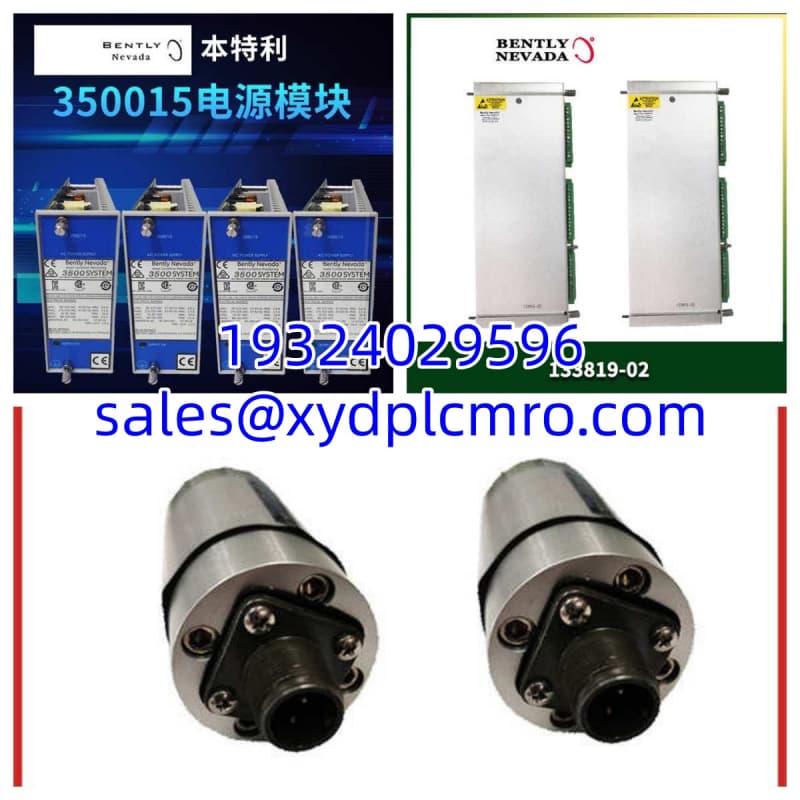
Installation & Configuration Guide
Preparation (10 min)
Verify the 3500 rack power supply has sufficient headroom. Each 149992-01 module draws significant current when all 16 relays are energized. Measure the backplane voltage at the target slot; it must be 24 VDC ±10%. Have the 3500 Rack Configuration Software ready on a connected laptop.Removal (5–10 min)
Power down the rack if possible, though 3500 modules support hot-swap. If hot-swapping, ensure the replacement module is pre-configured or the rack is set to accept new configurations automatically. Loosen the top and bottom captive screws. Pull the module straight out; do not rock it side-to-side.Installation (10 min)
Align the 149992-01 with the backplane connector. Slide it in smoothly until it seats fully. Tighten the captive screws to secure the module. Connect the field wiring to the terminal block. Double-check polarity on the 24 VDC input and verify no field wires are shorted to ground.Power-On & Test (10 min)
Power up the rack. Watch the module LEDs; the “OK” light should be solid green within 30 seconds. Open the configuration software and verify the module is recognized as a 3500/33. Force a single relay output to verify the field circuit responds. Check for any “Module Fault” or “Configuration Mismatch” alarms.
Troubleshooting Quick Reference
| Symptom | Probable Cause | Immediate Check |
|---|---|---|
| Module “OK” LED Off | No backplane power | Measure 24 VDC at backplane pins; check rack power supply. |
| Relay Clicks But No Field Voltage | Open field circuit | Measure voltage at relay contacts; check field fuse/breaker. |
| “Config Mismatch” Alarm | Wrong module type | Verify software config matches physical 149992-01 label. |
| Intermittent Relay Chatter | Loose field wiring | Torque terminal screws; check for vibration-induced loosening. |
| All Relays Stuck On | Logic error or short | Check for external short on common terminal; review logic map. |
Dimensions, Mounting & Wiring Notes
- Dimensions: 220 mm (H) x 140 mm (W) x 50 mm (D)
- Mounting: Standard 3500 full-height slot; secured by top/bottom captive screws.
- Wiring: Field connections via rear terminal block or front-access terminal adapter. Use 14 AWG to 22 AWG wire. Torque terminals to 1.1 N·m (10 in-lb). Ensure 25 A rating is not exceeded per contact; derate if multiple relays share a common bus.
FAQ
Can I use 149992-01 to replace a 3500/32 module?
Yes, but you must update the rack configuration. The 149992-01 occupies the same slot but presents 16 channels instead of 4. Your existing logic will map to the first 4 channels; the remaining 12 will be unconfigured until you program them.What’s the max load I can actually switch?
Stick to 25 A at 250 VAC resistive. For inductive loads like solenoids, derate significantly. I usually recommend keeping it under 10 A for inductive applications to extend contact life. (I once saw a 20 A inductive load weld contacts in three months.)Do I need to power cycle the rack to add this module?
No. The 3500 system supports hot-swap. However, if the rack is in a critical protection state, some sites require a maintenance window. Always follow your site’s specific safety procedures.Is this module compatible with 3500/92 communication gateways?
Yes. The 149992-01 is a standard 3500 I/O module. It communicates via the backplane to the 3500/22M or 3500/92 gateway. No special drivers are needed; it appears as a standard relay module in System 1 software.I’m getting a “Bad Module” alarm, what gives?
Check the backplane connector pins first. Bent pins or debris in the slot cause this 80% of the time. If pins look good, try the module in a different slot. If it follows the module, it’s likely a failed internal component.Can I buy this used?
You can, but verify the test report. Relay modules suffer contact wear. A used 149992-01 with 100,000+ operations may have degraded contacts. New original stock eliminates this risk entirely.Does it support TMR voting?
No. For Triple Modular Redundancy, you need the 3500/34 TMR Relay Module. The 149992-01 supports standard AND/OR logic but not hardware-based 2oo3 voting.





