 Tel:
Tel:  Email:
  WhatsApp:
 Description
Key Technical Specifications (For Spare Verification)
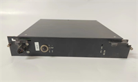
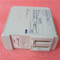
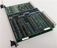
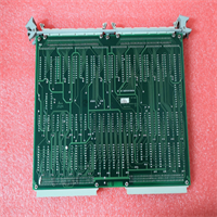
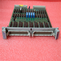
- Product Model: VMIVME-2510B
- Manufacturer: VMIC
- System Architecture: VME64x (32-bit data bus, A24/A32 addressing)
- Input Channels: 32 single-ended digital inputs
- Input Type: Optically isolated, suitable for dry contact or wet voltage sensing
- Input Voltage Range: Typically 10–60 V DC (field-side), compatible with common industrial logic levels
- Isolation Voltage: 500 V RMS or higher between field and VME backplane
- Response Time: < 10 µs typical (suitable for real-time sequencing)
- Connector Type: Front-panel 50-pin SCSI-II or DIN 41612 (varies by revision)
- Interrupt Support: Yes, programmable vector and level
- Conformance: IEEE 1014 (VMEbus), CE, FCC Class A
- Form Factor: 6U VME (233.35 mm × 160 mm)
System Role and Downtime Impact
The VMIVME-2510B is commonly deployed in power plant control panels, aerospace ground support equipment, and industrial test rigs where reliable monitoring of discrete field signals—such as valve positions, motor running status, or emergency stop contacts—is essential. It interfaces directly with the VME CPU (e.g., VMIVME-7452) to provide real-time status updates for logic solvers or simulation models. If this module fails, the host system may interpret all inputs as “open” or “closed,” leading to incorrect state decisions. In protection or interlock applications, this can trigger unnecessary trips or, more dangerously, fail to detect a hazardous condition. Because the module uses custom FPGA logic and VME-specific drivers, replacement requires an exact hardware revision match; even minor differences in interrupt handling or timing can cause system instability. Recovery is further complicated by the lack of modern diagnostic tools compatible with legacy VxWorks or Linux 2.4 environments.
Reliability Analysis and Common Failure Modes
Although designed for industrial environments, units in service since the late 1990s to mid-2000s now show predictable wear patterns:
- Optocoupler degradation due to cumulative current stress, leading to increased propagation delay or complete channel failure—often undetectable without channel-by-channel loopback testing.
- Input clamping diode or TVS device fatigue, reducing surge immunity and making the module vulnerable to field-side transients.
- Front-panel connector corrosion or solder joint cracking, especially in high-vibration or humid settings, causing intermittent signal loss.
- VME bus buffer IC failure, resulting in backplane communication errors that affect the entire chassis.
- PCB trace delamination near high-current return paths, exacerbated by thermal cycling over decades of operation.
A key weakness is the absence of per-channel diagnostics; most systems only detect total module failure, not individual channel drift. Preventive measures include periodic functional testing using simulated field signals, visual inspection for discoloration near optocouplers, cleaning of connectors with non-residue contact cleaner, and maintaining spare modules powered periodically to prevent capacitor “sleep death.”
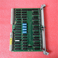
VMIC VMIVME-2510B
Lifecycle Status and Migration Strategy
The VMIVME-2510B has been obsolete for over a decade, with no official support or manufacturing from current rights holders. Continued use carries significant risk: untested surplus may pass basic continuity checks but fail under real-time load, and original driver source code is often unavailable for recompilation on updated OS kernels.
As an interim solution, organizations may:
- Source only from vendors providing full channel validation reports under live VME master control
- Implement external signal monitoring (e.g., PLC shadowing) to detect input discrepancies
- Maintain a matched spare with identical firmware PROM (if applicable) and revision number
For long-term sustainability, migration to modern alternatives is strongly advised. Options include:
- Curtiss-Wright VXI/VME digital I/O modules (e.g., VXI-2510-compatible successors) with extended lifecycle support
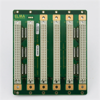
- Adlink or Elma VME64x I/O boards featuring enhanced diagnostics and software compatibility
- Hybrid solutions using VME-to-PCIe bridge chassis with contemporary I/O cards
Migration typically requires updating VME register access code, re-validating timing margins, and re-certifying safety functions—but ensures continued operational integrity, reduces mean time to repair (MTTR), and aligns legacy infrastructure with current embedded computing standards.