 Tel:
Tel:  Email:
  WhatsApp:
 Description
Key Technical Specifications
| Parameter | Specification |
|---|---|
| Input Voltage | 24VDC (Range: 19.2 – 30VDC) |
| Number of Points | 32 Inputs (4 Groups of 8) |
| Input Current | Typical 3mA per point @ 24VDC |
| Logic Type | Sink / Source (Configurable) |
| Response Time | ≤ 1ms (OFF to ON) |
| Isolation | 500V AC (Group to Group) |
| Power Dissipation | 1.7W + (0.36W x Active Channels) |
| Bus Current | 330 mA |
| Addressing | 2 Input Words |
| Protection | Reverse Polarity Protection |
Product Introduction
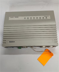
In the world of DCS and PLC maintenance, the Schneider 140DDI35300 is the “workhorse” of the Modicon Quantum rack. I’ve seen these modules installed in refineries that haven’t shut down in a decade. They don’t do fancy math, and they don’t handle motion control, but they do one thing perfectly: they tell the CPU if a switch is open or closed, reliably, millions of times a day.Why do engineers stick with this specific model? Density and Isolation. You get 32 points of logic in a single slot, which saves massive amounts of panel space. More importantly, the 4-group isolation (500V AC) means if a surge hits one group—say, from a faulty solenoid valve—it won’t fry the entire card or the backplane. It’s a rugged, discrete input module designed for the messy reality of industrial wiring. Just be careful with the “State 1” voltage; it needs a solid 11V DC to trigger, so don’t try to run it on a dying 12V battery.
Quality SOP & Tech Pitfalls (The Reality Check)
The Lab Report (SOP)
Before we ship a 140DDI35300, it goes through a “Live Test” protocol. We don’t just look at the LEDs.
- Visual Inspection: We check the DIN rail clips for brittleness (common in old stock) and inspect the terminal block pins for corrosion.
- Backplane Check: We verify the connector integrity on the 140XBP chassis to ensure it seats firmly.
- Full Load Test: We use a variable 24VDC power supply to energize all 32 channels simultaneously. We verify that the “State 1” current draw doesn’t exceed the spec (approx. 3mA/point) and that the bus current stays within the 330mA limit.
- Response Verification: We pulse the inputs at 1ms intervals to confirm the module catches fast signals without dropping packets.
The Engineer’s Warning (Pitfalls)
Here is where people get burned with this card:
- The “Source” vs. “Sink” Trap: This module is often wired as a “Sink” (negative logic), meaning the current flows into the module. If you wire it like a standard Source output, the logic will be inverted, or it won’t work at all. Always check the common terminal wiring.
- The “Ghost” Voltage: Because of the high input impedance (2.5kΩ internal resistance), I’ve seen technicians get false “ON” readings from induced voltage in long cable runs running parallel to power lines. If your logic is acting erratic, check for phantom voltage.
- Field Story: A plant in Texas called me because their “Emergency Stop” wasn’t tripping the PLC. It turned out the wiring was loose on the terminal block, but the LED was still faintly lit due to leakage current. The module was fine; the termination was garbage. Always torque your terminals.
Installation & Configuration Guide
Swapping a 140DDI35300 is straightforward, but don’t get cocky. One wrong wire and you pop the internal fuse or the input circuit.
- Pre-Installation (The “Photo” Phase):
- ⚠️ CRITICAL: Before you pull a single wire, take a high-resolution photo of the terminal block wiring. The labeling on these old cards can fade.
- Ensure the rack power is OFF. The Quantum backplane carries 5VDC and 24VDC; a short here can kill the CPU.
- Removal:
- Unlatch the terminal block (it’s removable, which is a lifesaver).
- Release the DIN rail clip at the bottom of the module.
- Slide the module out gently. Don’t yank it; the backplane connector is fragile.
- Installation:
- Insert the new 140DDI35300 into the slot. Ensure it clicks into the backplane.
- Re-wire: Match your wires to the photo you took. Double-check the polarity on the Common terminals.
- Torque: Tighten terminals to spec. Loose wires cause 90% of “intermittent fault” headaches.
- Power-On & Testing:
- Apply 24VDC field power first.
- Power up the rack. Watch the LEDs.
- Force Test: In Unity Pro (or Concept), force an input address to ‘1’. Verify the physical LED lights up. Then toggle it to ‘0’. If the LED stays on, you have a wiring short or a stuck relay in the field.
Compatible Replacement Models
If you can’t find a 140DDI35300, or if you’re upgrading the system, here is how the migration path looks.表格
| Compatibility | Model Number | Notes & Differences |
|---|---|---|
| ✅ Drop-in Replacement | 140DDI35300 | Exact match. Ensure the revision level supports your current firmware (Unity Pro v5.0+ recommended for CCOTF). |
| ⚠️ Hardware Compatible | 140DDI35310 | Similar 32-point module, but check the voltage rating and logic type (Source vs Sink). May require minor wiring changes. |
| ❌ Not Compatible | 140DDO35300 | DO NOT USE. This is a Discrete OUTPUT module. Plugging this in will short your field inputs and likely damage the card. |
Frequently Asked Questions (FAQ)
Q: Can I hot-swap this module while the PLC is running?
A: Generally, no. While the Quantum system supports CCOTF (Change Configuration On The Fly), standard discrete I/O modules like the 140DDI35300 are not typically designed for live removal unless you have specific redundant backplanes and firmware setups. If you pull it live, you risk arcing the backplane connector. Shut the rack down if possible.Q: My module LEDs are all flashing. What does that mean?
A: That’s usually a “Bus Fault” or a configuration mismatch. The PLC processor isn’t talking to the card correctly. Check your rack mapping in the software. If the LEDs are solid but the logic is wrong, check your Common wiring (Source vs. Sink).Q: Does this module have internal fuses?
A: No, the 140DDI35300 does not have internal fuses for the input points. It relies on external protection or the current-limiting nature of the 24VDC supply. If you short an input, you won’t blow the module, but you might trip your power supply.Q: What is the “State 1” voltage requirement?
A: To register as a logical “1” (ON), the input needs to see at least 11V DC. The “State 0” (OFF) must be below 5V DC. If your field sensors are outputting 8V, the module will ignore them.Q: Is the terminal block included?
A: If you buy “New Surplus,” the terminal block is usually attached. If you buy “Refurbished” or “Used,” verify if the terminal block is included. You can’t easily use the module without it.