 Tel:
Tel:  Email:
  WhatsApp:
 Description
Key Technical Specifications
| Parameter | Specification | Field Context |
|---|---|---|
| Input Voltage | 120/230V AC (50/60Hz) or 24V DC | Verify your plant power supply |
| Output Voltage | 5V DC (Backplane) / 24V DC (I/O) | Powers CPU and I/O modules |
| Redundancy | 1+1 (Hot-Swappable) | Seamless failover, no code download needed |
| Operating Temp | -15°C ~ 70°C | High-temperature tolerance for control panels |
| Protection | Overvoltage, Undervoltage, Short-Circuit | Built-in hardware protection |
| Dimensions | Standard Quantum Module Width | 25mm (approx) – fits in any slot |
| Certifications | UL, CSA, CE | Global industrial safety compliant |
Product Introduction
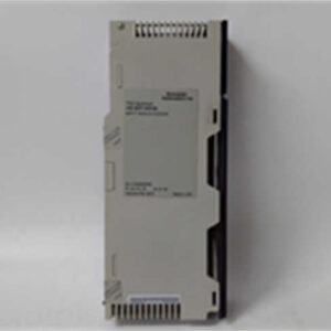
The 140CRA93200 is the unsung hero of the Modicon Quantum architecture. It is a Redundant Power Supply Module that ensures your PLC never loses its mind due to a power glitch. In the field, we call this a “1+1” setup—two power supplies feeding the same rack. If one fries (and they do, especially in noisy industrial environments), the other takes over instantly, and your process keeps running without a single heartbeat missed.This module is a marvel of industrial design. It features a dual-input design, meaning you can feed it from two separate breaker panels. If one breaker trips, the other keeps the lights on. The internal diode bridge ensures there is zero crossover time during the switchover. Unlike some modern “smart” power supplies, this is pure, hardened industrial hardware. It doesn’t have a web interface; it just works. The -15 to 70-degree Celsius operating range means it can survive the Siberian winter or the scorching heat of a steel mill control cabinet.
Quality SOP & Tech Pitfalls
The QA Process (What You Get)
When you receive this unit, it has been through the wringer. We start with a Visual Counterfeit Check to ensure the gold plating on the connectors is authentic and the laser etching is crisp. Next, it sits on our Live Test Rack for 24 hours to verify the firmware boots correctly and the redundancy logic functions. We use a Fluke 115 to check insulation resistance and ensure there is no leakage between the primary and secondary power inputs. Finally, we log the firmware version and package it in anti-static bags with desiccant.The Engineer’s Warning (The Reality Check)
Slot Number Mismatch: This is the #1 cause of installation failures. When configuring the redundancy in Unity Pro (or Control Expert), the Slot Number in the software MUST MATCH the physical slot in the chassis. If you tell the software the module is in Slot 2, but it’s in Slot 3, it will never sync. You will be staring at a flashing red light wondering why it won’t work.
Cable Swapping: The redundancy cable (the thin black cable that connects the two power supplies) is easy to swap during installation. Double-check that the cable is plugged into the correct port on the module. If you cross them, the modules will fight each other and fail to establish a master/slave relationship.
ESD Damage: These modules are sensitive to static. Always ground yourself before handling the module. A single zap can damage the internal MOSFETs, rendering the unit bricked.
Installation & Configuration Guide
Phase 1: Pre-Installation (Safety First ⚠️)
- Turn off the main breaker to the control panel and wait 5 minutes for capacitors to discharge.
- Take high-resolution photos of the terminal block connections and the redundancy cable routing.
- Label every cable connected to the module to avoid wiring confusion.
Phase 2: Removal
- Release the DIN clips on the left and right sides of the module.
- Gently pull the module straight out of the chassis. Do not twist.
Phase 3: Installation
- Insert the module into the empty slot in the chassis.
- CRITICAL: Connect the redundancy cable to the corresponding port on the second power supply before powering on.
- Secure the DIN clips to hold the module in place.
Phase 4: Power-On & Testing
- Restore 120/230V AC power to the panel.
- Watch the LED indicators. The “Run” light should be solid green; the “Redundancy” light should be solid green (indicating master) on one unit and flashing amber (indicating slave) on the other.
- Verify the output voltages (5V and 24V) with a multimeter to ensure they are within tolerance.
Compatible Replacement Models
Upgrade Path
- ✅ Drop-in Replacement: 140CRA93200. Same footprint, same functionality. (The industry standard for Quantum redundancy).
- ⚠️ Software Compatible: BMXCPS4002 (for M580). Requires reconfiguring the power scheme in the new IDE. (High labor cost, but offers higher efficiency).
- ❌ Hardware Mod Required: Modern Switching Power Supplies. These require rewiring to a separate PDU and a complete system overhaul. (Not recommended for a simple swap).
Frequently Asked Questions (FAQ)
Q: Can I hot-swap this module while the system is running?
A: Yes, but with extreme caution. The redundancy protocol allows it, but if you pull both power supplies at the same time, the CPU will reset. Best practice is to swap one at a time and monitor the “Redundancy” LED to ensure the slave takes over cleanly.Q: Is this module still supported by Schneider?
A: Officially, Schneider has moved on to the M580 series and newer power supplies. However, this 140CRA93200 is a workhorse. You can still find firmware updates on their portal, but spare parts for the chassis are becoming scarce. If you are buying this for a legacy system, you are buying reliability, not future tech.Q: What if the output voltage is low?
A: The output voltage is regulated by the internal power supply circuitry. If it reads low, first check the Input Voltage. If the input is within spec but the output is still low, the internal regulator is likely damaged. Replacement is expensive; consider using a buck-boost transformer on the input instead of replacing the module.Q: How do I know if it’s a genuine Schneider part?
A: Look for the laser-etched logo on the front panel. Counterfeit Quantum modules often have blurry text. Additionally, genuine units have a specific MAC address burned into the Ethernet chip (if applicable) that matches the serial number sticker. If they don’t match, it’s a fake.