 Tel:
Tel:  Email:
  WhatsApp:
 Description
Key Technical Specifications
| Parameter | Specification |
|---|---|
| Output Channels | 8 Independent Channels |
| Signal Type | Current (4-20mA, 0-20mA, 0-25mA) |
| Resolution | 12-bit to 16-bit (Configurable) |
| Backplane Current | 550 mA @ 5V DC |
| External Power | 6-30V DC (Typically 24V DC) |
| Power Consumption | 5.0 W |
| Isolation | Channel-to-Bus: 1780V DC (1 min) |
| Update Time | Typical 5 ms |
| Operating Temp | 0°C to +60°C |
| Certifications | UL 508, CSA C22.2, FM Class 1 Div 2 |
Product Introduction
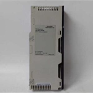
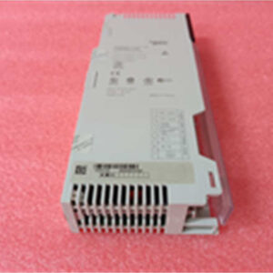
Let’s be honest, the Modicon Quantum platform is the “cockroach” of the automation world—it survives conditions that kill everything else. The 140ACO13000 is the standard workhorse for analog output in these racks. I’ve seen these modules sitting in cabinets that haven’t been cleaned since the 90s, covered in dust, still pushing 4-20mA signals to critical control valves without a hiccup.It’s not flashy. It doesn’t have an LCD screen. But for a process engineer, it’s reliable. It handles the heavy lifting for current loop devices. The key here is the 550mA backplane draw; it’s not a low-power module, so make sure your power supply budget can handle it if you are filling a rack. It supports “hot” configuration changes in the logic, which is a lifesaver if you need to tweak a setpoint range without shutting down the whole production line. Just keep it cool; anything over 60°C and you’re asking for trouble.
Quality SOP & Tech Pitfalls (The Reality Check)
The Lab Report (SOP)
Before we ship a 140ACO13000, we don’t just look at the box.
- Visual Inspection: We check the bus connector pins. Bent pins on the backplane are the #1 reason for “ghost” faults. We also check for battery corrosion leakage from adjacent modules.
- Live Rack Test: We install it in a Quantum chassis. We force a 50% output (approx 12mA) via the PLC logic and measure the physical terminals with a calibrated Fluke multimeter to ensure the Digital-to-Analog conversion is linear.
- Isolation Check: We run a Hi-Pot test (carefully) to ensure the 1780V isolation barrier between the bus and the field side is intact.
- Sealing: It goes into an anti-static bag with desiccant. Moisture is the enemy during shipping.
The Engineer’s Warning (Pitfalls)
Here is where people get burned. This module is not channel-to-channel isolated. If you have a ground loop issue on Channel 1, it can mess up the signal on Channel 2. I once spent three days troubleshooting a “noisy” signal on a valve positioner, only to realize the technician had tied the negative terminal of a different channel to a dirty ground. Always check your grounding scheme. Also, don’t mix voltage and current wiring if you are using a breakout board that supports both; the crosstalk can induce false readings.
Installation & Configuration Guide
1. Pre-Installation (Safety First)
- Power Down: Ideally, kill the rack power. While Quantum supports some hot-swap, why risk arcing the backplane?
- Discharge: Wait 30 seconds after power off for capacitors to discharge.
- Documentation: If replacing an existing unit, take a photo of the wiring. Do not trust the wire tags; they are often wrong.
2. Removal
- Unlatch the module from the DIN rail or chassis slot.
- Disconnect the field wiring terminal block (usually a removable plug).
- Slide the module out gently. If it sticks, don’t force it—check the locking tab.
3. Installation
- seating: Slide the 140ACO13000 into the slot. Ensure it seats firmly against the backplane. You should feel a solid “click” or resistance.
- Wiring: Reconnect your 4-20mA loops. Tighten the terminals. Loose wires cause resistance changes, which cause signal drift.
- DIP Switches: This module is mostly software-configured via Unity Pro or Concept software, but verify there are no legacy hardware jumpers if it’s an older revision.
4. Power-On & Testing
- Apply 24VDC external power.
- Check the LEDs. Green is good. Red means you have a configuration mismatch or a blown fuse on the output.
- Force an output in the logic (e.g., 4mA, 20mA) and verify with a multimeter at the terminal.
Compatible Replacement Models
| Compatibility | Model Number | Notes |
|---|---|---|
| ✅ Direct Drop-In | 140ACO13000 | Exact match. Ensure firmware revision is compatible with your Quantum CPU. |
| ⚠️ Check Specs | 140ACO23000 | Similar function but verify channel count and isolation specs. |
| ❌ Not Compatible | 140AVI03000 | This is an Input module (AI), not an Output. Do not install. |
Frequently Asked Questions (FAQ)
1. Can I hot-swap this module while the PLC is running?
Technically, the Modicon Quantum backplane supports it, but I wouldn’t recommend it unless you have redundant controllers. If you pull it out live, you will trip the outputs. If that valve slams shut, you might have a safety incident. Turn the power off.2. Why is the red LED flashing?
Usually, this means the “External Fault” bit is set. Check your wiring. You likely have an open circuit (broken wire) on one of the 4-20mA loops, or the external 24V power supply is sagging below 6V.3. Does this support 0-10V voltage output?
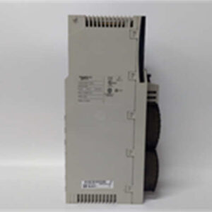
Be careful here. The 140ACO13000 is primarily a Current Output module (4-20mA). If you need 0-10V, you usually need a different model (like the 140AVO02000). Check the label on the side of the module. If it doesn’t explicitly say “Voltage,” assume it’s current only.4. What is the “550mA” rating for?
That is how much power the module steals from the PLC rack backplane to run its own processor and logic. If you have 10 of these in a rack, that’s 5.5 Amps just for the modules, before you even power the field devices. Size your power supply accordingly.5. Is this module isolated?
It is isolated from the Bus (protecting your PLC CPU from high voltage spikes), but the channels are not isolated from each other. They share a common ground reference. If you need total isolation, you need signal isolators on the field wiring.