 Tel:
Tel:  Email:
  WhatsApp:
 Description
Technical Specifications (For Spare Part Verification)
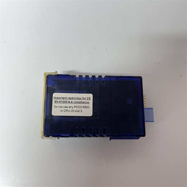
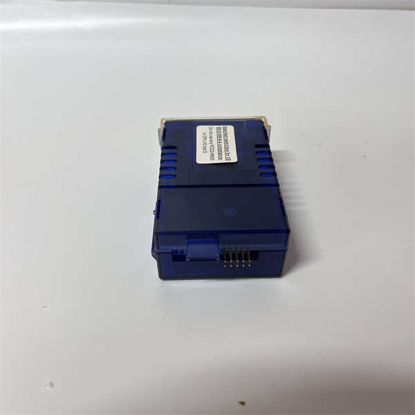
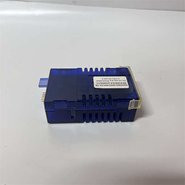
- Product Model: PCD3.R60X
- Manufacturer: SAIA-Burgess Controls (ABB)
- System Platform: SAIA PCD3 family (e.g., PCD3.Mxxx CPUs with PCD3.Cxxx backplanes)
- Output Channels: 8 independent changeover (SPDT) relays
- Contact Rating: 2 A at 250 VAC / 30 VDC (resistive load)
- Switching Voltage: Max 250 VAC / 30 VDC
- Electrical Isolation: 4 kV between coil and contacts; channels galvanically isolated from system logic
- Connector Type: Removable screw terminal block (Phoenix-style, 3.5 mm pitch)
- Operating Temperature: 0°C to +55°C
- Mounting: Snap-on to PCD3 base rail, hot-swappable in many configurations
- LED Indication: One per channel (ON = relay energized)
- Compatibility Note: Must be used with PCD3.C300 or higher I/O carrier modules; not compatible with PCD2
System Role and Downtime Impact
The SAIA PCD3.R60X is a final control element interface in PCD3-based automation systems, commonly deployed in district heating plants, commercial HVAC, and small-scale industrial processes. It directly energizes field devices that cannot be driven by solid-state outputs—such as motor starters, solenoid valves, or emergency shutdown relays.
Failure of this module typically results in loss of control over connected loads. For example, if used to switch a boiler enable circuit or a fire damper actuator, a stuck-open relay could prevent system startup, while a welded-closed relay might cause unsafe continuous operation. Because the PCD3.R60X often controls safety- or comfort-critical functions, its malfunction can trigger alarms, force manual override, or lead to complete subsystem shutdown. In unattended facilities (e.g., remote pumping stations), this may go unnoticed until a process deviation occurs.
Reliability Analysis and Common Failure Modes
Although robust for its era, the PCD3.R60X is now subject to age-related wear due to its reliance on mechanical components:
- Relay contact welding or erosion: Frequent switching of inductive loads (e.g., contactor coils) causes arcing, leading to contact welding (fail-safe closed) or increased contact resistance (intermittent open).
- Coil burnout: Voltage surges or prolonged overvoltage conditions can degrade the relay drive transistors or coil windings, rendering channels inoperative.
- Terminal block corrosion: In humid environments (e.g., boiler rooms), terminal screws and wire strands oxidize, increasing resistance and causing localized heating that accelerates failure.
A key design limitation is the absence of arc suppression on outputs—making the module more susceptible to contact degradation when switching inductive loads without external snubbers. As preventive maintenance, technicians should:
- Perform annual contact resistance tests using a low-resistance ohmmeter (< 100 mΩ expected).
- Inspect terminal blocks for discoloration or loose wires.
- Verify LED indicators match actual relay state during functional testing.
SAIA PCD3.R60X
Lifecycle Status and Migration Strategy
SAIA-Burgess (now integrated into ABB’s automation portfolio) has discontinued the PCD3.R60X, with no direct replacement in current ABB AC500 or Freelance product lines. Official support, including firmware updates or repair services, is no longer available. Remaining inventory exists only through third-party surplus channels, often without validation of relay cycle count or contact condition.
Short-term risk mitigation includes:
- Securing 1–2 tested spares with verified channel operation under load (not just LED check).
- Adding external RC snubbers or varistors on inductive outputs to extend relay life.
For long-term reliability, migration to modern platforms is recommended. Options include:
- Upgrading to the ABB AC500 series with TB560F relay output modules (8-channel, similar specs, but requires full reprogramming in Automation Builder).
- Replacing the entire PCD3 system with a compact PLC platform featuring certified relay outputs and enhanced diagnostics.
Because the PCD3.R60X is often embedded in custom control panels, any migration must account for wiring compatibility, enclosure space, and revalidation of all controlled safety functions. A staged approach—replacing one subsystem at a time—is advisable to minimize operational disruption.