 Tel:
Tel:  Email:
  WhatsApp:
 Description
Key Technical Specifications (For Spare Parts Verification)
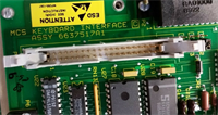
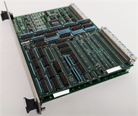
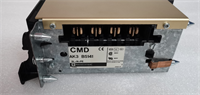
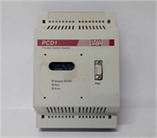
- Product Model: PCD1.M120
- Manufacturer: Saia-Burgess Controls AG
- Product Family: PCD1 Series (first generation)
- CPU Architecture: Proprietary 16-bit microcontroller
- Integrated I/O:
- 8 digital inputs (24 VDC)
- 4 digital outputs (relay or transistor, depending on variant)
- 2 analog inputs (0–10 V or 4–20 mA)
- 1 analog output (0–10 V)
- Program Memory: ~32–64 kB (EPROM or early flash, non-volatile but limited write cycles)
- Communication: RS-232 (programming/service port), optional RS-485 via expansion module
- Programming Software: PG4 (DOS/Windows 3.1/95 era); incompatible with modern operating systems without emulation
- Power Supply: 24 VDC ±10%
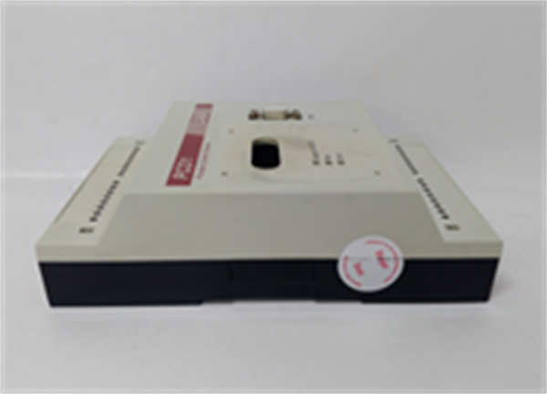
- Mounting: DIN rail, modular design supporting limited I/O expansion
- Standards: CE marked; compliant with EN 50081/50082 (EMC) for its time
System Role and Downtime Impact
The PCD1.M120 was widely deployed from the late 1980s through early 2000s in commercial buildings, university labs, small hospitals, and district energy substations. It commonly controlled air handling units, boiler sequencing, pump alternation, or lighting schedules—often as a standalone “black box” with minimal remote monitoring. In many legacy installations, it remains in service due to budget constraints or perceived reliability.
A failure halts all control logic instantly. For example:
- In a lab ventilation system, exhaust fans may stop, risking containment breaches.
- In a heating substation, mixing valves could freeze in position, causing overheating or freezing downstream.
- Without digital backup, restoring operation requires either a verified spare or re-engineering the entire control strategy—a process that can take days or weeks.
Because these systems rarely have redundancy, the PCD1.M120 represents a single point of failure with disproportionate operational impact.
Reliability Analysis and Common Failure Modes
Despite robust mechanical design, decades of service have revealed predictable aging issues:
Common failure modes include:
- EPROM/flash memory bit rot – program corruption after 20+ years, leading to boot failures or erratic logic execution.
- Internal power supply capacitor drying – causes voltage droop under load, triggering spontaneous resets or I/O dropout.
- RS-232 interface IC degradation – prevents firmware upload or diagnostics, locking out maintenance access.
- Relay contact welding (on output variants) – results in stuck-on signals, potentially damaging connected actuators.
- PCB trace delamination near high-current terminals due to thermal cycling, creating intermittent opens.
Design weaknesses:
- No real-time clock (RTC) or battery backup in most variants → time-based schedules fail after power loss.
- Minimal diagnostic LEDs – troubleshooting requires direct serial connection.
- No overvoltage protection on analog inputs – vulnerable to sensor wiring faults.
- Limited scan speed (~10–50 ms) – unsuitable for dynamic processes, but adequate for HVAC.
Preventive maintenance recommendations:
- If possible, extract and archive the PG4 project file using a legacy PC or DOS emulator.
- Perform annual functional tests of all I/O points using manual overrides or simulated inputs.
- Inspect terminal blocks for corrosion or loose connections—especially on 24 VDC power lines.
- Install external surge protection on field wiring to reduce stress on input circuits.
- Store spare units in climate-controlled, anti-static packaging with firmware pre-loaded (if feasible).
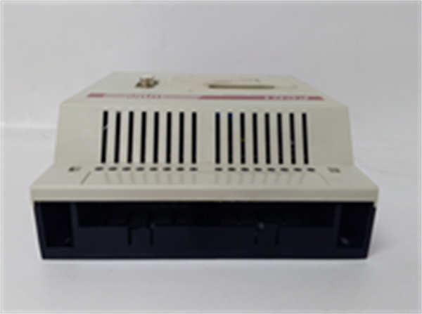
PCD1.M120 SAIA
Lifecycle Status and Migration Strategy
The PCD1 platform has been end-of-life for over 20 years. Saia-Burgess (now under Siemens) offers no repair services, firmware updates, or technical documentation for PCD1. Original programming tools run only on obsolete Windows versions, making recovery from failure extremely difficult.
Interim risk mitigation:
- Secure 1–2 tested spares with identical hardware revision and known-good firmware.
- Maintain a dedicated legacy PC (or virtual machine) with PG4 installed for emergency recovery.
- Document all I/O wiring and control logic manually if source code is unavailable.
Long-term migration path:
Upgrade to the PCD3.Mxxx series (e.g., PCD3.M2770) or integrate into a modern Siemens Desigo CC, Trend IQ4, or open BACnet/IP PLC platform. This involves:
Upgrade to the PCD3.Mxxx series (e.g., PCD3.M2770) or integrate into a modern Siemens Desigo CC, Trend IQ4, or open BACnet/IP PLC platform. This involves:
- Replacing CPU and I/O modules
- Rewiring field devices to new terminal layouts
- Recreating control logic in IEC 61131-3 (ladder, FBD, or ST)
- Updating SCADA/BA integration to BACnet MS/TP or IP
While capital-intensive, such a modernization eliminates obsolescence risk, improves cybersecurity, enables remote diagnostics, and ensures compliance with current energy codes.
For facilities with extended asset life plans, a phased replacement—starting with the most critical or frequently failing PCD1 nodes—is the most pragmatic approach to sustaining operational continuity while managing cost.