 Tel:
Tel:  Email:
  WhatsApp:
 Description
Key Technical Specifications
| Parameter | Specification |
|---|---|
| Input Voltage | 380 – 480 V AC (±10%) |
| Input Frequency | 50 – 60 Hz |
| Continuous Power | 15 kW (DC Bus) |
| Peak Power | 45 kW (0.3 seconds) |
| DC Bus Voltage | 320 V (Rated) |
| Dimensions | 150 mm (W) x 325 mm (H) x 355 mm (D) |
| Weight | 11.2 kg |
| Ambient Temp Range | 5°C to 45°C (Operational) |
| Cooling | Forced Air (Requires 80mm clearance on sides) |
| Protection Class | IP20 (Open Rack) |
Product Introduction
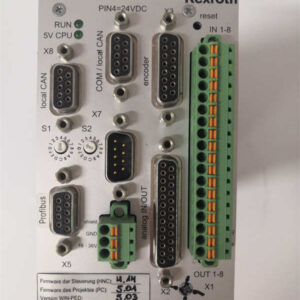
If you are working on an older Bosch Rexroth motion control system and you are staring at a failed power supply, the REXROTH TVD1.2-08-03 is likely the beast you are dealing with. This is a beast of a module—physically large and heavy, designed to handle the raw power needed for industrial servos.I’ve seen these modules in heavy-duty packaging plants and material handling systems. They are the workhorses that sit behind the drives, converting your plant’s 3-phase AC power into the clean, regulated DC bus voltage that the drives need to operate. It’s not just a power brick; it’s the heart of the electrical system for that specific machine. You can’t really “upgrade” it in the traditional sense because it’s so tightly coupled with the drive architecture, but finding a replacement is crucial for getting the line back up and running.
 Quality SOP & Tech Pitfalls (The Reality Check)
 Quality SOP & Tech Pitfalls (The Reality Check)
The Lab Report (SOP)
When dealing with a module this old, the testing isn’t just about firing it up; it’s about survival.
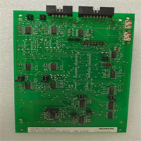
- Visual & Counterfeit Check: First, we inspect the PCB for signs of overheating, corrosion, or tampering. The capacitors are the most vulnerable component here. We check the date codes on the electrolytics to ensure they haven’t dried out.
- Insulation Resistance Test: Using a Megger (insulation resistance tester), we verify that the isolation between the AC input and DC output is intact. A failure here means a short circuit waiting to happen.
- Live Test on Test Rack: We power it up in a controlled environment. We monitor the startup sequence, the DC bus voltage regulation, and listen for any buzzing from the inductors. We also test the cooling fans to ensure they spin up to speed.
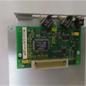
- Firmware/Version Logging: Since this is a discontinued part, we log the specific firmware version and control board revision. This ensures that when you install it, the drive firmware recognizes it correctly.
The Engineer’s Warning (Pitfalls)
- The “Hot Swap” Disaster: Do not attempt to swap this module while the system is live. The DC bus is going to be charged to 320V. Touching the terminals or inserting it into a live slot is a guaranteed way to blow fuses or destroy the drive. Always, always cycle the main breaker.
- Thermal Management: This module runs hot. The specs say it derates at 1°C (to 55% output) and at 6500 feet altitude. If your control cabinet is poorly ventilated or if you are running it in a high-temperature environment (like a steel mill), you are going to run into thermal faults. Make sure the air ducts are clear and the cooling fans are functioning.
Installation & Configuration Guide
Phase 1: Safety & Preparation
- Power Down: Shut off the main power breaker and the control power. Wait for the capacitors to discharge (usually 5-10 minutes).
- Lockout/Tagout: Ensure the breaker is locked out to prevent accidental re-energization.
- Document: Take photos of the wiring connections and the DIP switch settings on the front of the module. These are critical for reinstallation.
Phase 2: Removal
- Disconnect Cables: Carefully disconnect the 3-phase AC input cables and the DC bus output cables. Mark them clearly to avoid mixing up the phases.
- Remove Mounting Screws: Remove the screws securing the module to the DIN rail or mounting plate.
- Extract: Slide the module out of the slot. Be careful not to damage the surrounding components.
Phase 3: Installation
- Set DIP Switches: Configure the new (or repaired) module exactly as the old one was. Pay special attention to any addressing or configuration switches.
- Secure: Slide the module into the slot and tighten the mounting screws.
- Reconnect: Reconnect the 3-phase AC and DC bus cables. Double-check your wiring against your photos.
Phase 4: Power-On & Testing
- Visual Check: Before flipping the breaker, visually inspect for any loose wires or debris.
- Power Up: Restore main power. Watch the LED indicators on the front of the module. They should go through a normal startup sequence.
- Monitor: Once the drive is powered, monitor the DC bus voltage with a multimeter. It should stabilize at 320V. If you hear any buzzing or see smoke, kill the power immediately.
Compatible Replacement Models
Since this is a discontinued part, finding a “drop-in” replacement is challenging. You have a few paths, but they all involve trade-offs.
- ✅ Direct Replacement (Hard to Find): REXROTH TVD1.2-08-03/S100
- Verdict: The holy grail. If you can find one of these exact units (new surplus or refurbished), it is 100% compatible with zero configuration changes.
- ⚠️ Software Compatible (Upgrade Path): REXROTH PSR 250-2
- Verdict: A modern replacement drive that requires a firmware update to the drive it powers. This is a viable upgrade if you are willing to reconfigure the drive settings to match the new power module’s parameters.
- ❌ Hardware Incompatible: General Purpose VFDs (Variable Frequency Drives)
- Verdict: Do not use a standard VFD as a replacement. The TVD1.2-08-03 is a DC Bus power supply, not an AC drive. It provides a stable DC link for servos. A VFD would not regulate the voltage properly and would likely cause the system to fault immediately.
Frequently Asked Questions (FAQ)
- Q: Is this module still available new?
- A: No. This part number is discontinued. You will only find it as a “New Surplus” unit (formerly installed, returned, or excess inventory) or as a refurbished unit from a third-party vendor.
- Q: Can I replace just the power module, or do I need the whole drive?
- A: You can usually replace just the power module (TVD) if the servo drive itself is functioning. However, you must ensure the firmware on the drive is compatible with this specific power module revision.
- Q: What if my system requires more power than 15kW?
- A: You would need to upgrade the entire drive system. This specific TVD module is designed for a maximum of 15kW continuous output. Higher power applications require a different chassis and drive architecture.
- Q: What is the difference between TVD1.2-08-03 and TVD1.3-15-03?
- A: The “1.2” and “1.3” series refer to different power levels and form factors. The 1.3 series generally offers higher power density. If your system is designed for the 1.2 form factor, swapping to a 1.3 unit may require chassis modifications or different mounting brackets.
- Q: How do I know if this module is compatible with my specific drive model?
- A: Compatibility is usually confirmed by part number matching in the drive’s configuration software. Since this is an older part, the easiest way is to compare the physical dimensions and the pinout of the internal wiring harness to the failed unit.