 Tel:
Tel:  Email:
  WhatsApp:
 Description
Key Technical Specifications (For Spare Part Verification)
- Base Model: ND32-5610
- Full Order Code: ND32-5610VS-101-011-31
- VS: Voltage Sensing input type
- 101: Input voltage range (typically 110–250 V AC/DC)
- 011: Output interface (e.g., opto-isolated transistor or relay)
- 31: Mechanical/hardware revision or mounting variant
- Channels: Likely 8 or 16 isolated digital inputs (exact count requires physical verification)
- Input Type: Voltage-sensing (not dry contact); designed to detect presence/absence of control voltage (e.g., 125 V DC tripping circuits)
- Input Voltage Range: Commonly 88–265 V AC/DC (universal)
- Isolation: Galvanic isolation per channel (typically ≥2.5 kV)
- Output Interface: Optocoupled logic signals compatible with 24 V PLC inputs or proprietary backplane
- Mounting: DIN rail or panel-mount with screw terminals
- Indicators: LED per channel (ON/OFF status)
- Standards Compliance: Designed to meet IEC 60255 (for relay applications) and EN 50178 (industrial electronics)
-

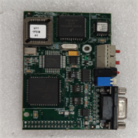
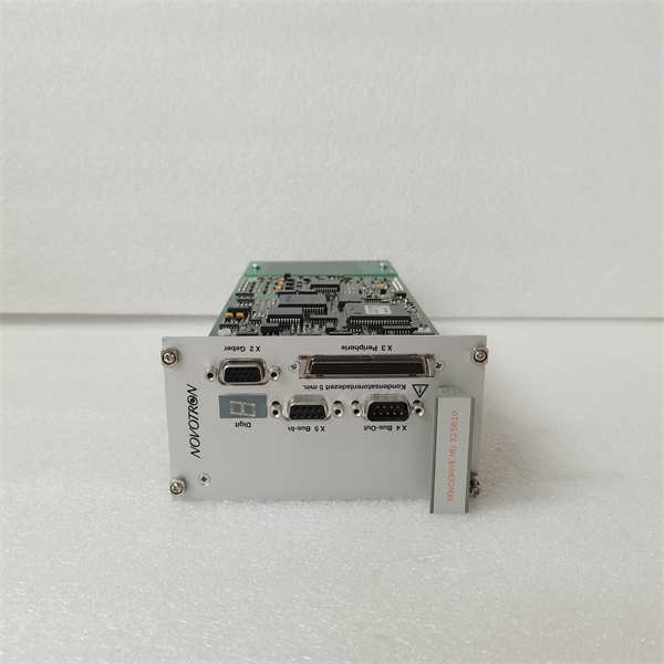
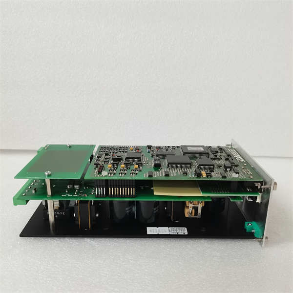
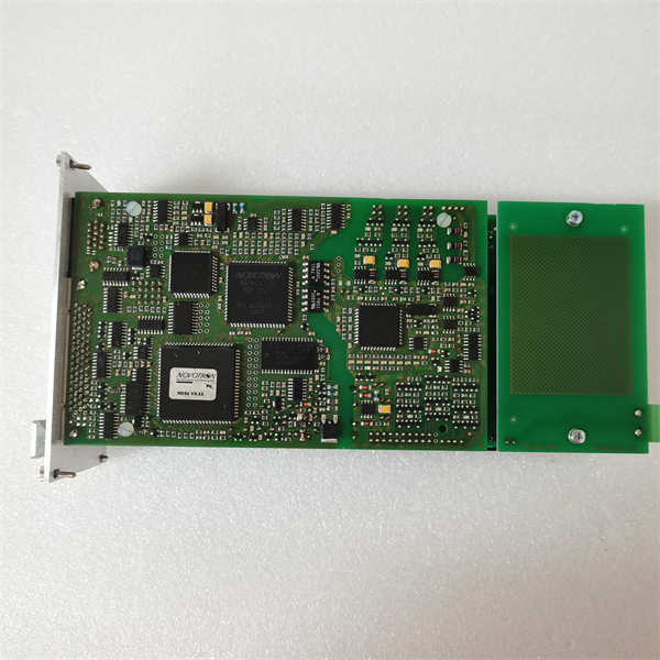
NOVOTRON ND32-5610 ND32-5610VS-101-011-31
System Role and Downtime Impact
The ND32-5610 was commonly integrated into custom-built protection, monitoring, or sequencing panels for hydroelectric plants, substations, and industrial power systems—often interfacing between high-voltage switchgear and logic controllers (e.g., Siemens S5, ABB Master, or relay-based schemes).
Its role includes:
- Monitoring circuit breaker “Closed”/“Open” status via auxiliary contacts energized by control voltage
- Detecting alarm conditions from protective relays (e.g., 86 lockout, 50N ground fault)
- Providing interlock feedback for motor starters or transfer switches
Failure modes can lead to:
- False “healthy” indications during actual faults
- Inability to initiate automatic sequences (e.g., backup generator start)
- Violation of safety interlocks, risking equipment damage or personnel hazard
Because these modules were rarely redundant, a single failure can compromise system integrity—especially in unattended or remote facilities.
Reliability Analysis and Common Failure Modes
Despite robust Scandinavian design, aging units exhibit:
- Optocoupler degradation: Reduced CTR (current transfer ratio) causes missed signal detection
- Input resistor drift: High-value input resistors age under continuous voltage stress, altering threshold sensitivity
- LED indicator burnout: Visual status loss (non-critical but complicates troubleshooting)
- Terminal block corrosion: Especially in humid or coastal environments
- PCB delamination or trace cracking: From thermal cycling over decades of service
Preventive actions:
- Perform functional tests using simulated control voltage
- Measure input current draw to verify resistor network health
- Inspect for discoloration or capacitor leakage (if any filtering caps present)
- Maintain detailed photos and wiring records for reverse-engineering if needed
NOVOTRON ND32-5610 ND32-5610VS-101-011-31
Lifecycle Status and Migration Strategy
Novotron Electronics AB is defunct, and all ND32-series products are unsupported and unobtainable new. No direct replacements exist from the original manufacturer.
Short-term mitigation:
- Search specialized European industrial surplus markets (e.g., Sweden, Germany) for used units
- Consider third-party reverse-engineered equivalents (rare but occasionally available)
- Implement external monitoring (e.g., auxiliary relays + modern DI modules) as a bypass
Long-term strategic path:
Replace the entire I/O subsystem with a modern, supported platform such as:
- Phoenix Contact AXC F 1152 (with inline I/O)
- WAGO 750 Series modular I/O
- Siemens SIMATIC ET 200SP
- ABB AC500 or AC800M with TU85x I/O
Migration steps include:
- Mapping each ND32-5610 input to a new digital input channel
- Rewiring field signals (often reusing existing multicore cables)
- Updating logic in the replacement controller
- Validating all interlocks and alarms per IEC 61511 or site safety procedures