 Tel:
Tel:  Email:
  WhatsApp:
 Description
Technical Specifications (For Spare Parts Verification)
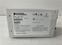
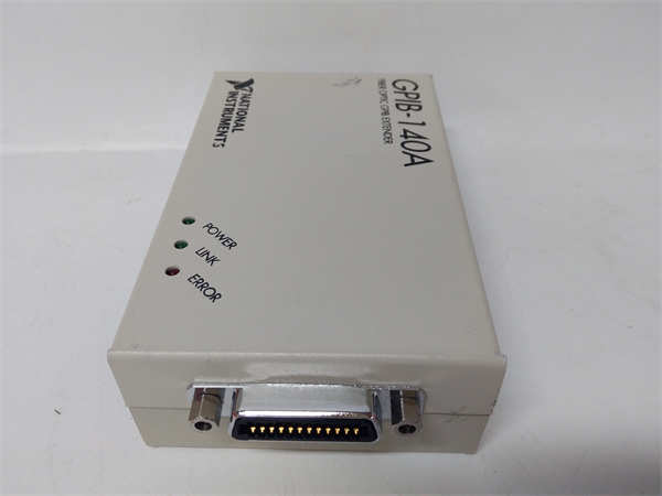
- Product Model: GPIB-140A
- Manufacturer: National Instruments
- Interface Standard: IEEE 488.1 (GPIB), compliant with ANSI/IEEE Std 488.1-1987
- Function: Active bus repeater/extender (not a controller or peripheral)
- Max Extended Distance: Up to 60 meters total bus length (vs. standard 20 m)
- Device Support: Maintains support for up to 15 devices across extended segments
- Power Requirement: +5 VDC via external power supply (included in original kit)
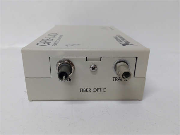
- Connector Type: Dual male/female 24-pin Centronics-style GPIB connectors
- Signal Regeneration: Yes – re-drives and reshapes GPIB signals to compensate for cable loss
- Operating Temperature: 0°C to 50°C
- Physical Form: Desktop or rack-mountable enclosure (no backplane mounting)
System Role and Downtime Impact
The GPIB-140A is typically deployed in legacy automated test equipment (ATE) systems used in aerospace, semiconductor, and defense manufacturing, where long-distance or high-device-count GPIB networks are required. It sits inline between the main GPIB controller (often an NI PCI-GPIB card in a PC) and distant instruments such as power supplies, spectrum analyzers, or multimeters. While not a processing unit, its role is critical for signal integrity over extended runs. If the GPIB-140A fails—due to power issues, connector damage, or internal logic faults—the entire downstream instrument chain becomes unresponsive. This halts automated test sequences, leading to production line stoppages, delayed R&D validation, or compliance testing bottlenecks, especially in environments where system re-architecture is not immediately feasible.
Reliability Analysis and Common Failure Modes
Although designed for lab environments, the GPIB-140A is prone to several age-related failure mechanisms. The most common issue is degradation of the external +5 VDC power adapter, which can output unstable voltage and cause intermittent bus resets or complete dropout. Internal electrolytic capacitors on the power regulation circuit often dry out after 15–20 years, leading to erratic behavior or failure to power on. Mechanical stress on the GPIB connectors—frequent mating/unmating or cable strain—can crack solder joints or damage contact pins, resulting in intermittent communication errors (e.g., “timeout” or “device not found”). A key design limitation is the lack of modern ESD protection; repeated handling without grounding can damage the bus transceiver ICs. For maintenance teams, recommended actions include inspecting power supply output under load, cleaning GPIB contacts with isopropyl alcohol, securing cables to reduce connector strain, and storing spares with protective caps on all ports.
-

NI GPIB-140A
Lifecycle Status and Migration Strategy
National Instruments officially discontinued the GPIB-140A many years ago and no longer provides drivers, firmware, or repair services. The product is absent from current NI documentation and compatibility tools. Continued use relies entirely on the secondary market, with increasing risk of receiving non-functional or misrepresented units. As a temporary measure, facilities may implement preventive stockpiling of verified-working units or use third-party board-level repair services. However, the sustainable path is migration to modern instrumentation interfaces. NI recommends replacing GPIB-based architectures with USB, Ethernet/LXI, or PXI/PXIe platforms. For existing GPIB instruments that must be retained, alternatives include using newer NI GPIB-USB-HS+ (779732-01) adapters with built-in signal conditioning or third-party active extenders that support longer distances via fiber (e.g., ICS Electronics models). Full migration requires updating test software (e.g., LabVIEW VIs) to use VISA over TCP/IP or USBTMC, but offers improved speed, reliability, and long-term supportability. Planning this transition during scheduled test system upgrades is strongly advised to avoid operational disruption.