 Tel:
Tel:  Email:
  WhatsApp:
 Description
Technical Specifications (For Spare Parts Verification)
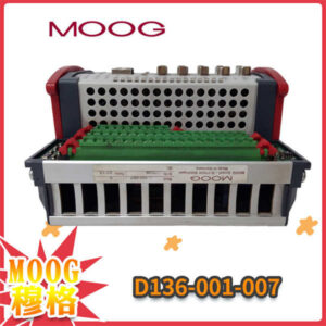
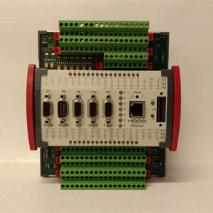
- Model: D136-001-007
- Manufacturer: MOOG Inc.
- System Family: MOOG D136 Series Servo Amplifiers
- Input Signal: ±10 V analog command
- Output Current: Typically ±50 mA to ±200 mA (valve-dependent)
- Power Supply: ±15 VDC, ±5% tolerance
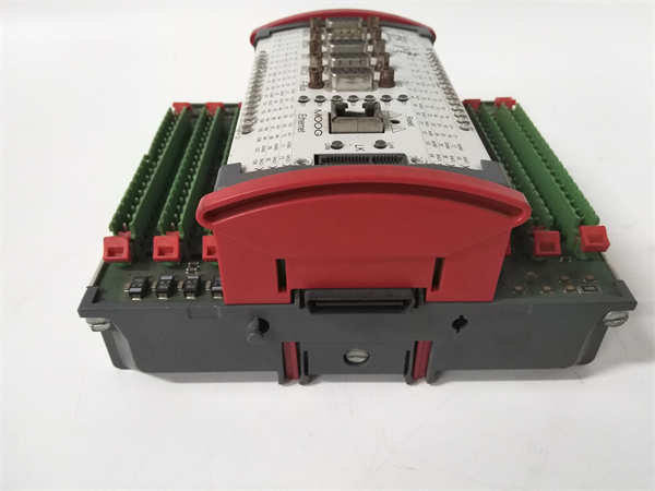
- Mounting Type: DIN rail or panel mount (via mounting brackets)
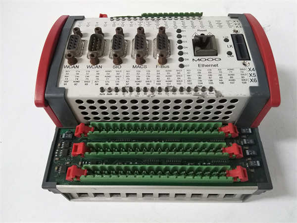
- Connector Type: Screw-terminal or plug-in header (varies by revision)
- Calibration Method: Internal potentiometers for gain, offset, and dither adjustment
- Environmental Rating: Designed for industrial control cabinets (IP20 equivalent)
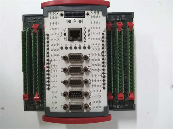
MOOG D136-001-007
System Role and Downtime Impact
The D136-001-007 serves as the analog interface between a motion controller (e.g., PLC or CNC) and a MOOG two-stage servo valve in hydraulic positioning systems. It is commonly found in legacy test rigs, flight simulators, metal forming presses, and turbine control systems. If this module fails, the associated hydraulic axis loses closed-loop control—leading to uncontrolled movement, safety interlock triggers, or emergency shutdowns. In continuous-process applications such as rolling mills or fatigue testing machines, its failure can halt an entire production cell for hours or days until a verified replacement is sourced and calibrated.
Reliability Analysis and Common Failure Modes
Despite its robust analog design, the D136-001-007 exhibits predictable aging patterns due to its reliance on discrete components. The most frequent failure modes include: drift in output offset due to aging operational amplifiers, intermittent connections from thermal cycling of terminal blocks, and complete output dropout caused by failed power regulators or damaged output transistors. A key design vulnerability is the absence of digital diagnostics—faults often manifest only as system-level performance degradation (e.g., oscillation, sluggish response), making root-cause analysis difficult without spare units for swap testing. Additionally, the unit lacks overvoltage protection on its analog input, rendering it susceptible to damage from EMI or wiring errors. For preventive maintenance, technicians should annually inspect terminal tightness, verify calibration against a known reference signal, and check for discoloration or bulging on internal electrolytic capacitors during cabinet servicing. Keeping a calibrated spare on-site is strongly advised.
MOOG D136-001-007
Lifecycle Status and Migration Strategy
MOOG officially discontinued the D136 series years ago, with no direct drop-in replacements. Continued use carries significant risk: authentic units are scarce, counterfeit or improperly refurbished modules are increasingly common, and technical support from MOOG is limited to paid legacy consultations. As a temporary measure, facilities may source tested units from specialized surplus vendors—but each must undergo full functional validation before installation. For long-term sustainability, migration to modern digital alternatives is recommended. MOOG’s current G-series (e.g., G122-1001-001) or iValve platforms offer superior performance, built-in diagnostics, and Ethernet-based configuration, though they require mechanical adaptation, updated cabling, and re-tuning of the control loop. Alternatively, third-party universal servo amplifiers with analog input compatibility (e.g., from Bosch Rexroth or Parker) can serve as functional substitutes, provided their bandwidth and current output match the original valve’s requirements. Any migration path necessitates thorough hydraulic system re-validation to ensure safety and performance compliance.