 Tel:
Tel:  Email:
  WhatsApp:
 Description
Key Technical Specifications
- System Compatibility: Metso DNA S4, S5, S6, and Valmet DNA systems.
- Communication Protocol: Metso DNA Bus, Profibus DP, or Foundation Fieldbus H1 (depending on specific backplane/variant).
- I/O Capacity: Typically supports up to 16-32 channels of mixed signals (depends on coupled I/O terminal boards).
- Processing: On-board microprocessor for local scaling, linearization, and simple logic (interlocks, sequencing).
- Power Supply: 24V DC nominal (Range: 19–30V DC). Often powered via the backplane or local terminal.
- Operating Temperature: -20°C to +70°C (-4°F to +158°F).
- Storage Temperature: -40°C to +85°C.
- Humidity: 5% to 95% non-condensing.
- Isolation: Galvanic isolation between bus, power, and I/O channels (typically 500V AC).
- Diagnostic LEDs: Status, Comm, Fault, Channel-specific indicators.
- Mounting: DIN-rail or specific Metso DNA rack chassis.
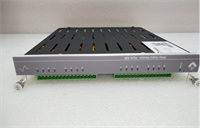
Product Introduction
In the Metso (now Valmet) DNA architecture, the IOP351 is the brain of the remote I/O station. Unlike “dumb” terminal blocks that just pass signals, this module actually processes data locally. I’ve used these in pulp mills and power plants where running hundreds of individual wires back to the main control room was impossible. The IOP351 sits in the field cabinet, aggregates the data, runs local interlocks (like pump start/stop logic), and sends only the essential data up the highway to the controller. This drastically reduces network traffic and controller scan time.The transition from “Metso” to “Valmet” branding can be confusing, but the hardware remains identical. If you see a unit labeled “Valmet,” it’s just newer stock. The IOP351 is robust, but its intelligence means it’s sensitive to firmware mismatches. If your DNA system was upgraded to version S6 and this module is stuck on an S4 firmware, it might refuse to communicate or report “Bad Quality” tags. Always check the firmware version before installing in a live, upgraded system. Also, these modules are often paired with specific terminal boards (like the IOB series); mixing incompatible terminal boards can cause pinout errors.
Quality SOP & Tech Pitfalls (The Reality Check)
The Lab Report (SOP)
We don’t just plug and play with DNA modules. First, we visually inspect the backplane connectors for bent pins—a common issue if the module was yanked out without releasing the locking mechanism. Then, we mount the IOP351 in a test DNA rack with a known-good power supply and communication master. We simulate digital inputs and analog currents (4-20mA) on the coupled terminal board and verify the values appear correctly in the DNA Studio engineering tool. We specifically test the “local logic” feature by forcing a logic condition and ensuring the output reacts without controller intervention. Finally, we check the diagnostic buffer for any historical hardware errors before sealing it.
The Engineer’s Warning (Pitfalls)
The classic mistake with the IOP351 is address configuration. These modules often use rotary switches or DIP switches on the front or side to set the Node ID on the fieldbus. If you swap a failed unit and forget to match the switch settings of the old one, the entire remote I/O drop goes offline. The controller will scream “Communication Loss” for every tag on that drop. Another pitfall: Power Sequencing. In some configurations, the IOP needs to boot up before the I/O terminals get power. If you power the terminals first, the module might latch up or misread the initial state of the inputs, causing a false trip. Always follow the specific power-up sequence defined in the DNA hardware manual. Also, beware of “ghost” voltages on unused digital inputs; floating inputs can toggle randomly. Tie unused inputs to ground or 24V as per the schematic.
Installation & Configuration Guide
Time Estimate: 30 Minutes (Swap & Address Set)
- Pre-Installation Safety ⚠️
- Notify operations that the specific I/O drop will be unavailable.
- Critical: Document the Node Address (rotary switch/DIP switch setting) and any jumper positions from the failed module. Take a photo.
- Verify the part number of the associated Terminal Board (IOB) to ensure compatibility.
- Removal
- Disconnect the 24V DC power to the I/O rack (if safe to do so; otherwise, proceed with extreme caution for hot-swap).
- Release the locking lever or screws securing the module to the rail/backplane.
- Pull the module straight out. Do not wiggle excessively to avoid damaging the backplane pins.
- Installation
- Set Address: Before inserting, set the rotary switches/DIP switches on the new IOP351 to match the documented address exactly.
- Check Jumpers: Verify any termination or configuration jumpers match the old unit.
- Seat the module firmly onto the backplane connector until it clicks or locks.
- Secure the locking mechanism.
- Power-On & Testing
- Restore 24V DC power.
- Observe the LEDs: “Power” should be steady green. “Comm” should flash or turn steady green once the handshake with the master is complete. “Fault” should be off.
- Open DNA Studio (or Valmet DNA Engineering Tool). Go online with the controller.
- Check the status of the I/O drop. It should show “Online” or “Good.”
- Force a test value on one input (e.g., short a digital input) and verify the change in the software monitor.
- Clear any latched alarms in the system.
IOP351 METSO
Compatible Replacement Models
- ✅ Drop-in Replacement: IOP351-X (Revision updates).
- Note: Valmet often releases revised hardware with the same model number but different suffixes (e.g., IOP351-2). These are generally backward compatible, but firmware may need updating to match the system version.
- ⚠️ Software Compatible: IOP350 (Previous Generation).
- Warning: Older model. Might fit physically but lacks the processing speed or memory for newer DNA features. Firmware conversion might be required. Not recommended for critical loops.
- ❌ Hardware Mod Required: IOP301 or IOP401 (Different Bus Type).
- Advice: Different communication protocols or form factors. Cannot be swapped without changing the backplane and re-engineering the network configuration.
Frequently Asked Questions (FAQ)
Is the IOP351 hot-swappable?
Yes, the Metso DNA system is designed for hot-swapping I/O modules. However, in practice, removing an active I/O processor will temporarily interrupt all signals on that specific drop. While the controller might hold the last value or go to a safe state, it will trigger alarms. It is best to perform the swap during a planned maintenance window or put the affected loop in “Manual” mode to prevent process upsets.How do I update the firmware on the IOP351?
Firmware updates are typically pushed from the DNA Studio engineering workstation. You connect to the system, select the module in the hardware tree, and choose “Download Firmware” or “Update.” Caution: This process resets the module. Ensure the process is in a safe state before initiating. You need the correct firmware file corresponding to your DNA system version (S4, S5, S6, etc.).What does a red “Fault” LED indicate?
A red Fault LED usually indicates a hardware failure, a configuration mismatch (e.g., the configured I/O types in software don’t match the physical terminal board), or a communication timeout. Check the diagnostic buffer in DNA Studio for the specific error code. Common causes include wrong node address settings or a defective backplane connection.Can I use this module with third-party I/O terminals?
Generally, no. The IOP351 is designed to work with specific Metso/Valmet IOB (I/O Board) terminal units that plug into its front or side. The pinout and communication protocol between the processor and the terminal board are proprietary. Using generic terminals will not work without complex custom wiring and even then, the diagnostics will fail.The module says “Valmet” but my system says “Metso”. Will it work?
Yes. Metso Automation’s industrial automation business was rebranded to Valmet in 2014. The hardware and software are continuous. A Valmet-branded IOP351 is the direct successor to the Metso-branded one and is fully compatible with existing Metso DNA systems, provided the firmware version is supported by your system software.