 Tel:
Tel:  Email:
  WhatsApp:
 Description
Key Technical Specifications
- Channel Count: 8 Independent Analog Output Channels.
- Output Signal: 4-20mA (Standard), configurable to 0-20mA or 0-10V (with external resistor/jumper, check manual).
- Resolution: 16-bit D/A Converter (High precision for valve positioning).
- Accuracy: ±0.1% of span at 25°C.
- Load Capacity: Max loop resistance typically 600Ω @ 24V supply (check specific voltage drop limits).
- Isolation: Channel-to-Channel isolation (250V AC) and Channel-to-Bus isolation. Prevents ground loops between devices.
- Communication Interface: Proprietary DNA Bus (connects to IOP114 or direct backbone).
- Diagnostics: Open loop detection, Short circuit protection, Under-range/Over-range flags.
- HART Support: Some revisions support HART pass-through or modulation for smart valve positioners (verify specific sub-model).
- Operating Temperature: 0°C to +60°C.
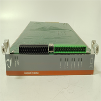
- LED Indicators: Per-channel status (Normal/Fault/Open), Module Run/Fault/Comm LEDs.
- Update Rate: Configurable, typically <50ms for all 8 channels.
Product Introduction
The IOP345 is the critical link between the Valmet/Metso DNA control logic and the physical process. While digital cards flip switches, the IOP345 precisely positions control valves that regulate steam flow, chemical dosing, or stock consistency in a paper machine. Its 16-bit resolution ensures that a 1% change in controller output results in a smooth, precise movement of the valve, avoiding the “hunting” or stiction issues seen with lower-resolution cards.A key feature of the IOP345 is its channel-to-channel isolation. In older systems, a ground fault on one valve loop could drag down the reference for an entire bank of outputs, causing multiple valves to slam shut or open. The IOP345 isolates each of the 8 channels, so a fault on Channel 1 stays on Channel 1. This is vital for safety and process stability. Like other Metso DNA modules, units manufactured before 2013 bear the “Metso” logo, while newer stock says “Valmet.” They are functionally identical, but always verify if your specific application requires HART communication capabilities, as early non-HART revisions of the IOP345 exist.
Quality SOP & Tech Pitfalls (The Reality Check)
The Lab Report (SOP)
Analog output cards demand rigorous linearity and load testing.
- Visual Inspection: Check for signs of overheating near output drivers and verify terminal screws are not stripped.
- Linearity Test: We command 0%, 25%, 50%, 75%, and 100% output on all 8 channels simultaneously into a precision load box (250Ω). We measure the mA output with a calibrated multimeter. Deviation must be <±0.1%.
- Load Regulation Test: We vary the loop resistance from 0Ω to 600Ω while holding a 50% command. The current output must remain stable within spec despite the changing load voltage drop.
- Open Loop Detection: We physically disconnect one channel while commanding output. The module must flag an “Open Circuit” alarm within 1 second.
- HART Verification (if applicable): If the card supports HART, we connect a HART communicator to verify it can pass signals to a smart positioner without distorting the 4-20mA control signal.
The Engineer’s Warning (Pitfalls)
Beware the “Passive vs. Active” loop confusion. The IOP345 is typically an active output device (it sources the 24V power for the loop). If you connect it to a field device that is also powered externally (a 4-wire transmitter mistakenly wired as an input, or a smart positioner with its own supply wired incorrectly), you create a voltage conflict that can damage the output driver. Always verify the field device wiring diagram: 2-wire loops get power from the card; 4-wire devices usually need the card configured for current sink mode (if supported) or external wiring adjustments.
Also, watch out for ground loops in shielded cables. Since the IOP345 offers channel isolation, you have flexibility, but if you ground the cable shield at both the field device and the cabinet end, and the field device ground potential differs from the cabinet ground, current will flow through the shield and induce noise. Best practice: Ground the shield at the cabinet end only (near the IOP345), leaving the field end floating, unless the device manufacturer specifies otherwise.
Installation & Configuration Guide
Time estimate: 30 minutes (includes loop checking).
- Pre-Installation
- ⚠️ SAFETY: De-energize the 24V DC supply to the I/O rack if possible. If hot-swapping, ensure the connected valves are in a safe failure position (e.g., fail-closed) or manually overridden.
- Document Wiring: Photograph the terminal block. Note which terminals are Signal (+) and Return (-) for each channel.
- Verify Jumpers: Some IOP345 versions have jumpers to select Voltage vs. Current mode or HART enable/disable. Match these to the old card or project spec.
- Removal
- Disconnect field wiring carefully. Label every wire (e.g., “AO-01+”, “AO-01-“).
- Release the module locking lever.
- Pull the module straight out.
- Installation
- Set Configuration: Ensure any hardware jumpers match the required mode (usually Current 4-20mA).
- Seat the new module firmly. Lock the lever.
- Re-connect wires. Double-check polarity. Reversing polarity on a 2-wire loop will result in 0mA output and potential diagnostic alarms.
- Torque terminals to spec (0.5–0.7 Nm).
- Power-On & Testing
- Energize the system.
- LED Check: “Run” LED steady green. No “Fault” LEDs.
- Loop Check: From the DNA Operator Station, set the output to 4mA (0%). Measure at the terminal block with a multimeter. It should read ~4.00mA.
- Step Test: Ramp the output to 20mA (100%). Verify the field valve moves fully open (or as per action). Check for linearity at 50% (12mA).
- Diagnostic Clear: Acknowledge any “Module Replace” alarms.
IOP345 METSO
Compatible Replacement Models
| Model Number | Compatibility Tier | Notes |
|---|---|---|
| IOP345 | ✅ Drop-in Replacement | Standard 8-channel analog output. Verify HART capability if needed. |
| IOP345-01 / -02 | ✅ Drop-in Replacement | Hardware revisions. Improved component reliability. Direct swap. |
| Valmet IOP345 | ✅ Drop-in Replacement | Rebranded unit post-2013. Fully compatible. |
| IOP344 | ⚠️ Check Specs | Often 4-channel or different isolation specs. Physical fit may be same, but capacity differs. |
| IOP346 | ❌ Different Type | Typically Analog Input module. Pinout and function differ. Do not use. |
Frequently Asked Questions (FAQ)
Can I use the IOP345 to drive a 0-10V signal?
The primary design is for 4-20mA current loops. Some revisions allow conversion to 0-10V by installing a precision resistor (typically 500Ω) across the output terminals and configuring the software scale accordingly. However, this reduces the drive capability and accuracy. For critical 0-10V applications, a dedicated voltage output module is preferred. Check the specific hardware manual for your revision before attempting this.Why is my valve not moving even though the output reads 12mA on the card?
If the card measures 12mA at its terminals but the valve doesn’t move, the issue is downstream. Check for:
- Open wiring: A broken cable between the cabinet and the valve.
- High resistance: Corrosion at the field junction box adding too much resistance, causing the voltage drop to exceed the card’s compliance limit.
- Valve Positioner: The positioner might be in “Local” mode, failed, or calibrated incorrectly. Bypass the positioner and inject mA directly into the valve actuator (if possible) to isolate the fault.
Does the IOP345 support HART communication?
Specific revisions of the IOP345 (often denoted by a suffix or specific ordering code) support HART pass-through. This allows the DNA system to communicate with smart valve positioners (e.g., reading feedback, diagnosing stiction) over the same 4-20mA wires. If your application requires HART, ensure you purchase the HART-enabled version. Non-HART versions will still control the valve (4-20mA) but cannot exchange digital diagnostic data.What happens if I short the output terminals?
The IOP345 has short-circuit protection. If a channel is shorted, the module will limit the current to a safe level, flag a “Short Circuit” alarm for that specific channel, and continue operating the other 7 channels normally. Once the short is removed, the channel typically recovers automatically or after a reset command, depending on configuration.How do I calibrate the output?
Hardware calibration is rarely needed due to the high stability of the 16-bit DAC. Calibration is typically performed in the Valmet DNA Engineering Station software by adjusting the “Zero” and “Span” scaling factors in the control strategy or I/O configuration block. Only perform hardware trim (if available via dip switches/software) if the module fails the linearity test by a significant margin (>1%).