 Tel:
Tel:  Email:
  WhatsApp:
 Description
Key Technical Specifications
| Parameter | Specification |
|---|---|
| System Compatibility | Metso DNA / Valmet DNA (Versions 5.x to 8.x) |
| Input Signal Types | Thermocouples (J, K, T, E, R, S, B, N, C) & mV (±10mV to ±100mV) |
| Channel Count | Typically 8 channels per module (high density versions may vary) |
| Resolution | 24-bit Sigma-Delta ADC (High precision for low-level signals) |
| Accuracy | ±0.1% of span or ±0.5°C (whichever is greater, typical) |
| Cold Junction Compensation (CJC) | Internal automatic compensation per channel or group (±0.5°C accuracy) |
| Isolation | Channel-to-Logic: 2500 VAC; Channel-to-Channel: Often isolated or group isolated (Check specific rev) |
| Update Rate | Configurable (100ms to 1s per channel, slower than standard AI due to filtering) |
| Diagnostics | Open wire detection (burnout), Short circuit, Range violation, CJC fault |
| Burnout Direction | Configurable (Upscale or Downscale on wire break) |
| Operating Temp | -20°C to +60°C (Module ambient affects CJC accuracy) |
| Communication | Proprietary DNA Fieldbus (Redundant capable) |
| Mounting | Metso DNA Rack Slot (DIN Rail compatible) |
Product Introduction
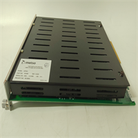
The IOP341 is the specialized “thermometer” of the Metso DNA I/O family. While the IOP303 handles standard 4-20mA loops, the IOP341 is engineered specifically for the microvolt-level signals generated by thermocouples. In processes like boiler superheat control, digester cooking, or paper machine steam showers, temperature accuracy is paramount. The IOP341 eliminates the need for external transmitters by connecting directly to the thermocouple, performing the complex linearization and Cold Junction Compensation (CJC) right on the card.This direct connection reduces potential points of failure and cost but demands higher immunity to noise. The IOP341 excels here with high-resolution 24-bit conversion and robust filtering algorithms that reject electrical interference common in mill environments. A standout feature is its granular diagnostic capability: it can detect an open thermocouple wire instantly and drive the output to a safe “upscale” or “downscale” value (configurable), preventing the controller from reacting to a sudden drop to ambient temperature as a real process event. One crucial detail often overlooked: the module’s own ambient temperature affects CJC accuracy. Ensure the cabinet ventilation is adequate; if the IOP341 overheats, your temperature readings will drift even if the sensor is perfect.
Quality SOP & Tech Pitfalls (The Reality Check)
The Lab Report (SOP)
Testing the IOP341 requires a high-precision temperature calibrator (like a Fluke 754 with a TC simulator head). We simulate various thermocouple types (K, J, T) across their full ranges, injecting precise mV signals corresponding to specific temperatures (e.g., 0°C, 100°C, 500°C). We verify the reported digital value matches the simulated temperature within the ±0.5°C spec. We specifically test the Cold Junction Compensation by varying the ambient temperature around the module (using a heat gun carefully) while holding the input constant, ensuring the reading remains stable (compensating for the change). We also trigger “wire break” alarms by disconnecting inputs and verifying the configured burnout direction (Up/Down) activates immediately.
The Engineer’s Warning (Pitfalls)
The Wrong TC Type Trap. This is the most frequent and dangerous error. A Type K thermocouple generates a different voltage than a Type J at the same temperature. If your field sensor is Type K but the DNA Studio configuration is set to Type J, your temperature reading could be off by tens of degrees. Always double-check the color code of the thermocouple extension wire and the tag documentation against the hardware configuration in DNA Studio before commissioning.Extension Wire Errors. You cannot use standard copper wire to extend a thermocouple signal to the IOP341. You must use matched Thermocouple Extension Wire (e.g., KX for Type K). Using copper wire creates new junctions at the terminal block, introducing unknown voltages that ruin the measurement. Also, ensure the polarity is correct (+ to +, – to -); reversing a TC wire results in a reading that drops as temperature rises.Ground Loops and Noise. Thermocouple signals are tiny (microvolts). Ground loops are devastating. If the thermocouple tip is grounded (common in industrial probes) and you ground the shield at the cabinet end too, you create a loop. The IOP341 has isolation, but severe ground potential differences can still introduce noise or damage the input. Best practice: Use ungrounded (isolated tip) thermocouples where possible. If grounded tips are unavoidable, ensure the IOP341 channel isolation is intact and consider using a head-mounted transmitter instead of direct wiring if noise persists.CJC Accuracy. Remember, the module compensates based on its own temperature. If the cabinet is hot (e.g., 50°C) due to poor ventilation or nearby heat sources, the CJC works harder, and any gradient across the module terminals can cause errors. Keep the I/O cabinet cool and ensure airflow is uniform across the rack.
Installation & Configuration Guide
- Pre-Installation ⚠️
- Identify Sensor Type: Confirm the Thermocouple type (J, K, T, etc.) for every channel. Check the tag list and physical wire coloring.
- Verify Extension Wire: Ensure you have the correct grade of TC extension wire (e.g., KX, JX). Do not use copper.
- Backup DNA Project: Save the current hardware configuration.
- Check Burnout Settings: Decide on Upscale or Downscale behavior for wire breaks based on safety logic requirements.
- Removal
- Label all TC wires clearly (Tag Number, +, -, Shield). Note polarity carefully.
- Disconnect the fieldbus cable.
- Unlatch and remove the module.
- Installation
- Insert the new IOP341 module into the rack and lock it.
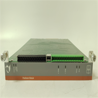
- Wire with Care: Connect the TC extension wires to the terminals. Strict Polarity: Red is usually Negative (-) in US standards, Blue in IEC. Verify your local standard. Tighten terminals gently; over-torquing can damage the small terminals.
- Shielding: Connect the shield to the ground bar at the cabinet end only. Do not let the shield touch the terminal screws.
- Reconnect the fieldbus cable.
- Power-On & Configuration
- Power up the segment. Check LEDs.
- In DNA Studio, open the Hardware Tree.
- Configure Channels: For each channel, select the correct Thermocouple Type (J, K, T…), set the Engineering Units (°C/°F), define the Range, and set the Burnout Direction (Upscale/Downscale).
- Download the hardware configuration.
- Validation: Measure the actual temperature at the sensor (if accessible) or simulate a known mV signal at the terminal block. Compare the HMI/Studio reading. It should match within tolerance.
- Check for “Open Wire” alarms if any channels are unused (terminate unused inputs properly if required).
IOP341 METSO
Compatible Replacement Models
| Compatibility Tier | Model Number | Notes |
|---|---|---|
| ✅ Drop-in Replacement | IOP341 | Exact match. Must configure TC types correctly in software. |
| ⚠️ Software Compatible | IOP341 (Older Rev) | Hardware identical. May require firmware update for newer DNA versions. |
| ⚠️ Successor Model | Valmet DNA I/O Series 4/5 (Temperature) | Newer generation. Higher density, potentially better CJC. Requires project migration and possibly new baseplates. |
| ❌ Incompatible | IOP303 (Standard Analog) | Designed for mA/V, not mV/TC. Lacks CJC and sufficient resolution for direct TC connection. Will give erroneous readings. |
Frequently Asked Questions (FAQ)
Can I mix different Thermocouple types on one IOP341 module?
Yes, typically the IOP341 allows configuration of each channel independently. You can have Channel 1 as Type K and Channel 2 as Type J, provided you configure them correctly in DNA Studio. However, verify this capability for your specific firmware revision, as very old revisions might have had group constraints.What happens if I use copper wire instead of TC extension wire?
You will get incorrect temperature readings. Copper wire creates a new thermocouple junction at the point where it connects to the TC wire (usually at the terminal block). Since the IOP341 measures the voltage relative to its own internal CJC, this extra junction introduces an unmeasured voltage error proportional to the temperature difference between the field and the cabinet. The error can be significant (several degrees per 10°C difference).Why is my temperature reading drifting slowly?
- Cabinet Temperature Change: If the cabinet temperature fluctuates wildly, and the CJC isn’t perfectly tracking (or there’s a thermal gradient across the module), readings can drift. Improve cabinet climate control.
- Moisture: Moisture in the terminal block or junction box can cause leakage currents affecting low-level mV signals. Check for condensation.
- Sensor Degradation: The thermocouple itself might be drifting due to age or chemical exposure.
Do I need to calibrate the IOP341 periodically?
The IOP341 is a digital device with stable components. Formal calibration is rarely needed unless specified by strict quality protocols (e.g., ISO). However, periodic verification (checking a few points against a handheld calibrator) is good practice, especially after a module replacement or if process anomalies suggest sensor drift. The scaling is done in the DNA logic, so replacing the card doesn’t inherently require recalibration if the new card is within spec.Can the IOP341 handle RTDs (Pt100)?
No. The IOP341 is designed for Thermocouples (mV) and generic mV signals. RTDs (Resistance Temperature Detectors like Pt100) require a different measurement principle (current injection to measure resistance). Metso/Valmet typically used a different module (e.g., IOP342 or similar specific RTD module) for RTD inputs. Connecting an RTD to an IOP341 will result in meaningless readings. Check your specific part number and datasheet to confirm.