 Tel:
Tel:  Email:
  WhatsApp:
 Description
Key Technical Specifications
- Channel Count: 32 Digital Channels (Typically configurable as Input or Output, or fixed mix depending on sub-model).
- Signal Type: Dry Contact, Wet Contact (24V DC), or Pulse Input.
- Voltage Rating: 24V DC Nominal (Operating range 18–30V DC).
- Current Capacity: Approx. 0.5A to 1.0A per output channel (check specific load ratings); Total module current limit applies.
- Input Impedance: Typically >3 kΩ for 24V inputs.
- Communication Interface: Proprietary DNA Bus (connects to IOP114 or direct to backbone depending on architecture).
- Isolation: Channel-to-bus isolation; Group isolation common (channels often grouped in banks of 8 or 16).
- Operating Temperature: 0°C to +60°C.
- LED Indicators: Per-channel status LEDs (On/Off/Fault), Module Run/Fault/Comm LEDs.
- Mounting: DIN Rail or specific Metso DNA rack chassis (slots into I/O carrier).
- Diagnostics: Open circuit detection, Short circuit protection (on outputs), Over-temperature warning.
Product Introduction
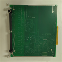
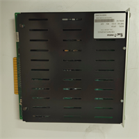
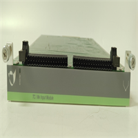
The IOP304 is the “muscle” of the Metso/Valmet DNA system when it comes to discrete control. While the IOP114 acts as the brain for a cluster, the IOP304 is where the rubber meets the road—connecting to limit switches, solenoid valves, motor start feedbacks, and emergency stops. In paper mills and power plants, space in the cabinet is premium real estate. The IOP304’s ability to pack 32 channels into a single slim form factor was a game-changer when released, cutting wiring time and panel footprint in half compared to older relay-based or lower-density cards.One critical detail engineers often miss: The IOP304 is often configurable. Depending on the firmware and the specific ordering code, a single hardware unit might be software-configured to be all Inputs, all Outputs, or a split (e.g., 16 DI / 16 DO). If you swap a card and suddenly 16 valves stop working while 16 switches start reading backwards, you likely installed a blank/default unit that hasn’t been configured to match the old card’s personality. The “Metso” branding on older units is identical in function to the newer “Valmet” branded replacements, but always verify the configuration data before commissioning.
Quality SOP & Tech Pitfalls (The Reality Check)
The Lab Report (SOP)
Digital I/O cards seem simple, but field noise makes them tricky.
- Visual Inspection: Check for burnt components near the terminal interface (sign of shorted outputs) and verify the backplane connector pins are straight.
- Channel Loop Test: We use a programmable power supply and load bank to cycle every single channel. For outputs, we switch a 24V/0.5A load on/off 100 times and measure voltage drop. For inputs, we simulate dry/wet contacts and verify logic threshold recognition (typically <5V for Off, >15V for On).
- Short Circuit Protection Test: We intentionally short an output channel to ground and 24V. The module must trip the channel, flag a diagnostic alarm, and ideally allow auto-reset or manual reset without damaging the driver IC.
- Cross-Talk Verification: We toggle adjacent channels at high frequency (10Hz) while monitoring a quiet channel to ensure no signal bleeding occurs.
- Configuration Match: We read the module’s internal configuration register and compare it against the project’s I/O database to ensure it matches the intended DI/DO split.
The Engineer’s Warning (Pitfalls)
Beware the “Common” terminal trap. The IOP304 usually groups channels into commons (e.g., 8 channels share one 24V return or ground). I’ve seen technicians wire all 32 channels assuming they are individually isolated. When a short occurred on Channel 1, it blew the fuse for the whole group of 8, taking down critical safety loops that were thought to be independent. Always check the wiring diagram for the specific Common terminal grouping before energizing.
Also, watch out for inductive kickback. If you are driving solenoid valves or relays directly from the IOP304 outputs, you must have flyback diodes or snubbers installed at the load or terminal block. Without them, the voltage spike from de-energizing a coil can punch through the output transistor and damage the entire module bank. The internal protection is fast, but not infinite against repeated inductive spikes.
Installation & Configuration Guide
Time estimate: 30 minutes (includes wiring verification).
- Pre-Installation
- ⚠️ LOCKOUT/TAGOUT: De-energize the 24V DC supply to the I/O rack. Even though it’s low voltage, a short during installation can arc and damage the backplane.
- Document Wiring: Take photos of the terminal block wiring. Note which terminals are “Common” (+24V or 0V) and which are individual signals.
- Verify Configuration: If replacing a failed card, confirm the replacement IOP304 has the same DI/DO configuration. If it’s a “blank” unit, you may need to download the configuration from the Valmet DNA engineering station before putting it into service.
- Removal
- Disconnect field wiring from the terminal block (if removable) or unscrew carefully if hard-wired. Label every wire.
- Release the module locking lever.
- Pull the module straight out.
- Installation
- Set Jumpers/Switches: Some IOP304 versions have hardware jumpers for input type (sinking/sourcing). Verify these match the old card.
- Seat the new module firmly into the slot. Lock the lever.
- Re-connect wires. Double-check polarity on the Common terminals. Reversing the common supply will prevent all channels in that bank from working.
- Torque terminals to spec (usually 0.5–0.7 Nm).
- Power-On & Testing
- Energize the 24V DC supply.
- LED Check: The module “Run” LED should be steady. Individual channel LEDs should reflect the actual field state (e.g., limit switches closed = LED On).
- Force Test: From the DNA Operator Station, “Force” an output On/Off. Verify the physical device (valve/light) reacts and the module LED changes.
- Diagnostic Clear: Acknowledge any “Module Replace” or “Config Mismatch” alarms in the system.
IOP304 METSO
Compatible Replacement Models
| Model Number | Compatibility Tier | Notes |
|---|---|---|
| IOP304 | ✅ Drop-in Replacement | Standard model. Verify DI/DO configuration ratio. |
| IOP304-01 / -02 | ✅ Drop-in Replacement | Hardware revisions. Generally interchangeable; firmware may auto-update upon insertion. |
| Valmet IOP304 | ✅ Drop-in Replacement | Rebranded unit post-2013. Fully compatible with Metso DNA systems. |
| IOP303 / IOP305 | ⚠️ Check Pinout | Different channel densities (16 or 64 ch). Physical size may differ; check chassis slot compatibility. |
| IOP3xx Series (Analog) | ❌ Incompatible | Analog modules have different pinouts and electronics. Do not insert into digital slots. |
Frequently Asked Questions (FAQ)
Can I mix 24V DC and 120V AC signals on the same IOP304?
No. The IOP304 is designed specifically for 24V DC logic levels. Applying 120V AC to these terminals will instantly destroy the input/output circuitry. For AC signals, you need a dedicated AC digital input module or an external interposing relay to step down the voltage to 24V DC.Why do some channel LEDs stay off even though the device is active?
Check the “Common” power supply for that group of channels. If the common 24V return or source is disconnected or blown, none of the channels in that bank will light up or function, even if the field device is sending a signal. Also, verify the wiring polarity; if the module is configured for “Sinking Input” and you wired it for “Sourcing,” it won’t detect the signal.How do I configure the DI/DO split on the card?
This is typically done via the Valmet DNA Engineering Station (or Metso DNA Studio). You select the hardware node, choose the IOP304 module, and define the channel types in the hardware configuration tree. Once downloaded, the module initializes with that specific map. Some older hardware versions might require physical jumper settings for coarse configuration (e.g., all DI vs. all DO), so check the hardware manual for your specific revision.Is the IOP304 hot-swappable?
Yes, in a redundant DNA system architecture, the IOP304 can typically be hot-swapped. However, removing the card will temporarily lose visibility and control of those 32 points. Ensure the process is in a safe state before pulling the card. The system should detect the removal and re-insertion automatically, but you may need to acknowledge alarms.What does a flashing “Fault” LED indicate?
A flashing Fault LED usually points to a configuration mismatch (the card doesn’t match what the server expects), a communication error with the parent processor (IOP114), or an internal hardware failure (like a blown output driver). Check the system diagnostic log for specific error codes (e.g., “Short Circuit Ch 4” or “Config Error”).