 Tel:
Tel:  Email:
  WhatsApp:
 Description
Key Technical Specifications
| Parameter | Specification |
|---|---|
| System Compatibility | Metso DNA / Valmet DNA (Versions 5.x to 8.x) |
| Signal Type | Analog Input (AI) and/or Analog Output (AO) |
| Channel Count | Typically 8 or 16 channels per module (configurable) |
| Resolution | 16-bit Sigma-Delta ADC/DAC |
| Input Ranges | 0-20 mA, 4-20 mA, 0-5 V, 0-10 V, ±10 V (Software selectable/jumper dependent) |
| Output Ranges | 0-20 mA, 4-20 mA, 0-10 V |
| Accuracy | ±0.1% of full scale (typical at 25°C) |
| Isolation | Channel-to-Logic: 2500 VAC; Channel-to-Channel: 500 VAC (Group isolated) |
| Update Rate | Configurable (10ms to 100ms per channel) |
| Diagnostics | Wire break detection, short circuit, range violation, cold junction compensation (for TC) |
| Operating Temp | -20°C to +60°C |
| Communication | Proprietary DNA Fieldbus (Redundant capable) |
| Mounting | Metso DNA Rack Slot (DIN Rail compatible in remote cabinets) |
Product Introduction
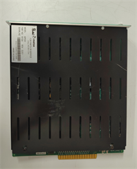
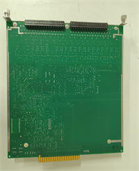
While the IOP302 handles the digital on/off world, the IOP303 is the precision instrument of the Metso DNA family, dedicated to the analog signals that define process quality. In a paper machine headbox or a boiler drum level control loop, noise and drift are enemies. The IOP303 tackles this with high-resolution 16-bit conversion and powerful onboard processing that filters out electrical noise right at the source, ensuring the main controller sees a clean, stable process value.Like its digital cousin, the IOP303 is an “intelligent” device. It doesn’t just pass raw bits; it can perform linearization for non-linear sensors (like differential pressure flow meters) and cold junction compensation for thermocouples locally. This reduces the load on the main CPU and improves overall loop stability. A key feature I rely on is the detailed wire-break and short-circuit detection. If a transmitter fails or a cable gets cut, the IOP303 flags it immediately with a specific quality bit, allowing the control logic to bumpless transfer to a safe state rather than reacting to a wild sensor spike. Just remember: unlike the digital IOP302, analog modules often need careful grounding and shielding practices to maintain that specified accuracy.
Quality SOP & Tech Pitfalls (The Reality Check)
The Lab Report (SOP)
Testing an IOP303 requires precision equipment, not just a logic probe. We use a calibrated Fluke 754 documenting process calibrator to inject precise current (4.000 mA, 12.000 mA, 20.000 mA) and voltage signals into every channel. We verify the digital value reported to the DNA station matches the input within the ±0.1% spec. For output channels, we command specific values and measure the actual current/voltage at the terminals under load (250-500 ohms). We also simulate “wire break” conditions by opening the loop to ensure the diagnostic bit trips instantly. Finally, we check crosstalk by driving one channel to max while monitoring adjacent channels for noise injection.
The Engineer’s Warning (Pitfalls)
The Ground Loop Nightmare. The most common failure mode for the IOP303 isn’t hardware defects; it’s poor installation causing ground loops. Because these modules handle low-level analog signals, connecting the shield to ground at both the field device and the IOP303 end can create a circulating current that introduces 50/60Hz hum into your readings. Rule of thumb: Ground the shield at the field device end only, and leave the cabinet end floating (or connected via a capacitor/grounding clamp if required by specific EMC directives). If you see your process value oscillating by 0.5% at 60Hz, check your shields first.Configuration Mismatch. The IOP303 is highly configurable. A module set up for 4-20mA inputs will read garbage (or fault) if you connect a 0-10V signal without changing the hardware jumpers (if applicable) and the software configuration in DNA Studio. Unlike digital cards where “on” is “on,” analog cards must match the physical signal type exactly. Always verify the “Engineering Units” and “Range” settings in the DNA hardware database match the physical jumpers/terminals before powering up. Also, be wary of “legacy” IOP303s that might not support the newer high-speed update rates required by modern control strategies in DNA v8.
Installation & Configuration Guide
- Pre-Installation ⚠️
- Backup DNA Project: Save the current hardware configuration and control logic.
- Verify Signal Type: Check the label on the old module and the datasheet of the field instruments. Is it 4-20mA? 0-10V? Thermocouple?
- Check Jumpers/Terminals: Some IOP303 variants require physical jumpers to select voltage vs. current mode. Ensure the new module matches the old one physically.
- Power Down: Safely isolate the I/O segment power.
- Removal
- Label all analog signal wires clearly (Tag number, +, -, Shield).
- Disconnect the fieldbus communication cable.
- Unlock and slide the module out.
- Installation
- Set Hardware Config: If the module has DIP switches or jumpers for range selection, set them now to match the application.
- Insert the module into the rack and lock it.
- Wire Carefully: Connect signal wires. Crucial: Terminate shields correctly (usually to a separate ground bar, not the terminal screw, unless using specific shielded terminals). Ensure polarity is correct (+ to +, – to -).
- Reconnect the fieldbus cable.
- Power-On & Testing
- Power up the segment. Check LEDs (Power, Comm, Fault).
- In DNA Studio, go online. The module should appear green.
- Calibration Check: With the field loop open or at a known state (e.g., transmitter at 0%), verify the reading in the HMI/Studio matches expectations.
- Force Test: If safe, force an output value (for AO channels) and measure at the terminal.
- Diagnostics: Simulate a wire break (disconnect one wire briefly) to confirm the system alarms correctly.
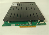
IOP303 METSO
Compatible Replacement Models
| Compatibility Tier | Model Number | Notes |
|---|---|---|
| ✅ Drop-in Replacement | IOP303 | Exact match. Must match specific sub-type (AI, AO, or Mixed) and firmware version. |
| ⚠️ Software Compatible | IOP303 (Older Rev) | Hardware identical. Requires firmware update via DNA Maintenance Tool for newer DNA versions. |
| ⚠️ Successor Model | Valmet DNA I/O Series 4/5 (Analog) | Newer generation. Higher density and speed but requires project migration and potentially new base plates. Not a direct swap. |
| ❌ Incompatible | IOP302 | Digital only. Cannot process analog signals. Physical fit might be similar, but functionally useless for analog loops. |
Frequently Asked Questions (FAQ)
What is the difference between IOP302 and IOP303?
The IOP302 is designed primarily for Digital (Discrete) I/O (switches, solenoids, motors). The IOP303 is designed for Analog I/O (process variables like pressure, temperature, flow). They have different internal circuitry and cannot be互换ed for their respective signal types.Can the IOP303 handle Thermocouples (TC) or RTDs directly?
Standard IOP303 modules typically handle voltage and current signals. For Thermocouples or RTDs, Metso/Valmet often used specific variants (sometimes labeled IOP303-TC or similar) or required external transmitters to convert the resistance/mV signal to 4-20mA before entering the IOP303. Check the specific part number on the label; if it says “Universal” or lists mV/Ohm ranges, it might support direct connection. Otherwise, use a transmitter.My analog reading is noisy/unstable. How do I fix it?
- Check shielding: Ensure cable shields are grounded at one end only (usually the field end).
- Check grounding: Ensure the IOP303 chassis and the cabinet ground are solid.
- Check for VFD interference: Are analog cables running parallel to Variable Frequency Drive power cables? Separate them.
- Enable filtering: In DNA Studio, you can often increase the digital filter time constant for the channel to smooth out noise (at the cost of response speed).
Do I need to recalibrate the IOP303 after replacement?
Generally, no. The scaling (e.g., 4mA = 0 Bar, 20mA = 10 Bar) is done in the DNA control logic/database, not inside the IOP303 hardware. The IOP303 just provides the raw digital count. Once you download the hardware config and logic, the scaling applies automatically. However, always verify the reading against a known standard (handheld calibrator) to ensure the new card’s ADC is within tolerance.Is the IOP303 still supported by Valmet?
Yes, Valmet supports the legacy Metso DNA I/O series, including the IOP303, with spares and firmware updates. However, for new expansions, Valmet typically recommends their latest DNA I/O series, which may require a system upgrade.