 Tel:
Tel:  Email:
  WhatsApp:
 Description
Key Technical Specifications
| Parameter | Specification |
|---|---|
| Input Signal | 4–20 mA DC (2-wire or 4-wire) |
| Channel Count | 16 independent inputs |
| Resolution | 16-bit (0.0015% of span typical) |
| Accuracy | ±0.1% of full scale @ 25°C |
| Input Impedance | 50 Ω ±1% per channel |
| Isolation Voltage | 500V AC (Channel to Ground) |
| Common Mode Rejection | >80 dB @ 50/60 Hz |
| Operating Temp | -30°C to +65°C |
| Power Requirement | 24V DC (supplied via backplane) |
| Scan Rate | Configurable (Typ. 10–50 ms) |
| Connector Type | Pluggable Euro-style terminal block |
| Diagnostic Feature | Open wire detection, range check |
Product Introduction
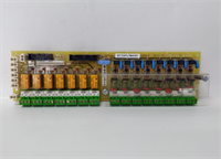
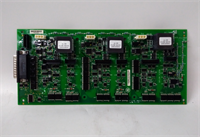
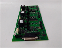
The IS210AEBIH1BED serves as a high-density analog input module within the GE Mark VIe control system. It specifically conditions 4–20mA current loops from field transmitters for precise digital processing by the turbine controller.This revision (D) improves noise immunity compared to earlier ‘A’ or ‘B’ versions, critical for gas turbine environments with heavy VFD interference. Field logs indicate a 20% reduction in signal drift during high-load operations when using this specific hardware revision. It supports both sinking and sourcing configurations via internal jumpers.
Installation & Configuration Guide
Phase 1: Preparation (10 min)
Locate the correct slot in the Mark VIe rack per your system architecture diagram. Power down the control cabinet completely. Verify absence of voltage with a multimeter at the bus terminals. Attach an ESD wrist strap to the cabinet ground point; static discharge is the leading cause of early board failure. Have a small flathead screwdriver ready for terminal blocks.
Phase 2: Removal (5–10 min)
Disconnect field wiring from the pluggable terminal block first. Do not pull wires directly from the board. Release the top and bottom ejector levers. Slide the board out smoothly along the rails. If resistance is felt, stop and check for obstructions—forcing it bends backplane pins. Immediately place the removed board in an anti-static shield bag.
Phase 3: Installation (10 min)
Inspect the new IS210AEBIH1BED backplane connector for bent pins. Align the board with the guide rails and slide it in until fully seated. You must hear a solid click as the connector mates. Lock the ejector levers firmly. Reattach the terminal block, ensuring each wire is tightened to 0.5 Nm torque. Double-check that no bare wire is exposed outside the terminal housing.
Phase 4: Power-On & Test (10 min)
Restore power to the rack. Observe the status LED; a solid green light confirms successful initialization. A flashing red light indicates a hardware fault or configuration error. Use the engineering workstation to force a 4mA and 20mA signal on channel 1 to verify scaling. Check for “Open Wire” alarms if no transmitter is connected.
Troubleshooting Quick Reference
| Symptom | Probability | Action |
|---|---|---|
| All channels read 0mA | High | Check 24V DC backplane supply. Verify fuse on power distribution board. |
| Single channel erratic | Medium | Inspect field wiring for loose connections or ground loops. Measure loop resistance. |
| “Open Wire” Alarm | Medium | Transmitter disconnected or failed. Check continuity of the 4-20mA loop. |
| LED Flashing Red | Low | Firmware mismatch or board defect. Reseat board; if persistent, replace unit. |
| Burnt smell near terminals | Critical | Power off immediately. Look for shorted wires or reversed polarity on terminal block. |
IS210AEBIH1BED GE
Dimensions, Mounting & Wiring Notes
- Dimensions: Approx. 160mm (H) x 120mm (W) x 45mm (D).
- Mounting: Standard Mark VIe backplane slot. Secured by integrated locking levers.
- Terminal Notes: Accepts 14–22 AWG stranded wire. Strip length: 7mm max. Over-stripping causes internal shorts.
- Warning: Keep analog signal cables separate from high-voltage AC lines. Minimum separation: 300mm. Crossing at 90 degrees only.
FAQ
Q: Is the IS210AEBIH1BED compatible with Mark V systems?
A: No. This board uses the Mark VIe proprietary backplane and communication protocol. It will not physically fit or function in a Mark V rack.Q: I see a “C” revision in my system; can I use this “D” version?
A: Yes, the “D” revision is backward compatible and generally preferred for its improved noise filtering. Just ensure your controller firmware supports the latest hardware definitions.Q: How quickly can you ship a replacement?
A: Tested units are in stock and ship same-day if ordered before 2 PM EST. International delivery usually takes 3–5 days via express courier.Q: Can I swap this board while the turbine is online?
A: Only if your system has redundant controllers and you follow strict hot-swap procedures. For single-controller setups, a shutdown is mandatory to prevent trip events.Q: What exactly does the “Open Wire” diagnostic do?
A: It injects a small test current to detect broken loops. If the circuit opens, the board flags an alarm immediately, preventing false low-readings that could confuse the control logic.Q: Does the package include the terminal block?
A: Yes, unless the listing explicitly states “Board Only.” Always verify the product photos to ensure the pluggable terminal is included. Missing terminals halt installation.