 Tel:
Tel:  Email:
  WhatsApp:
 Description
Key Technical Specifications
| Parameter | Specification |
|---|---|
| Input Voltage | 24V DC coil drive (from backplane) |
| Contact Rating | 5A @ 250V AC / 5A @ 30V DC (Resistive) |
| Relay Type | Electromechanical, Form C (SPDT) |
| Channels | 16 independent outputs |
| Isolation | 2500V RMS between coil and contacts |
| Mounting Type | Mark VIe Backplane Slot |
| Operating Temp | -30°C to +65°C |
| Indicator LEDs | Per-channel energized status |
| Connector Type | Euro-style terminal blocks (3-tier) |
| Protection | Flyback diodes on coil inputs |
| Weight | Approx. 1.2 kg |
| Compliance | CE, UL, CSA (Check specific unit label) |
Product Introduction
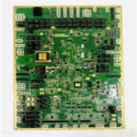
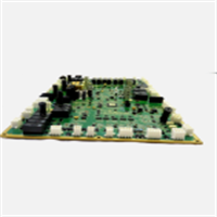
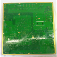
The IS200WETBH1ABA functions as a high-density relay interface within the GE Mark VIe control system, converting low-voltage logic signals from processor cards into isolated high-power switching actions. It is primarily used for emergency shutdown (ESD) circuits and auxiliary equipment control.This board distinguishes itself through “wet” relay architecture, meaning external power sources switch through the contacts rather than relying on internal logic voltage. This design ensures fail-safe operation even if the control logic power fails. Field records show these units typically handle over 100,000 mechanical operations before contact wear becomes a concern. (Note: The “H1” revision often includes updated snubber circuits compared to earlier “A” versions).
Installation & Configuration Guide
Preparation (10 min)
- Execute Lockout/Tagout (LOTO) on all power sources feeding the relay contacts.
- Verify the IS200WETBH1ABA revision matches the system engineering specification.
- Prepare tools: #2 Phillips screwdriver, wire strippers, multimeter, ESD strap.
Removal (5–10 min)
- Disconnect all field wiring from the three tiers of terminal blocks. Label every wire.
- Remove the two mounting screws securing the board to the rack.
- Pull the module straight out from the backplane.
- Real-world detail: Check the backplane pins for green corrosion; clean with contact spray if the cabinet was exposed to humidity.
Installation (10 min)
- Align the IS200WETBH1ABA guides with the rack slots.
- Push firmly until the backplane connector seats fully. You should feel a distinct click.
- Reinstall mounting screws. Torque to 1.5 Nm.
- Reconnect field wiring. Ensure tightness to prevent arc tracking.
Power-On & Test (10 min)
- Restore control power (24V DC) to the rack.
- Verify the “Power” LED on the associated processor card is green.
- Force individual relay outputs via the HMI or toolbox software.
- Measure continuity across the relay contacts to confirm closure/opening. Listen for the audible “click.”
Troubleshooting Quick Reference
| Symptom | Probability | Action |
|---|---|---|
| Relay won’t energize | High | Check 24V DC supply to the backplane. Verify logic output from processor card. |
| Contacts welded shut | Medium | Inspect load current. If >5A, external interposing relay was required. Replace board. |
| LED on but no output | Medium | Multimeter check across terminals. Likely bad contact or broken wire. |
| Intermittent operation | Low | Reseat the board. Check for loose terminal screws causing vibration issues. |
| Coil chatter | Low | Input voltage dropping below 18V DC. Check power supply capacity margin. |
IS200WETBH1ABA GE
Dimensions, Mounting & Wiring Notes
- Dimensions: Approx. 160mm (H) x 120mm (W) x 90mm (D) — Verify with physical caliper measurement.
- Mounting: Standard Mark VIe backplane slot.
- Terminal Notes: Use stranded wire (18–12 AWG). Ferrules mandatory for vibration zones.
- Clearance: Maintain 75mm clearance in front for wiring access and heat dissipation.
- Warning: Do not route high-voltage AC wires parallel to low-voltage logic wires within the same conduit.
FAQ
Q: Can I swap this with an IS200WETBH1AAA?
A: Usually yes, but verify the schematic. The “B” revision often has minor component updates for noise immunity. Check the GE hardware compatibility matrix first.Q: What does “Wet Relay” actually mean?
A: It means the relay contacts switch an external power source provided by you, not power generated by the board itself. This isolates the control logic from the high-power load.Q: I heard these relays fail often. Is that true?
A: Not if sized correctly. Most failures come from switching inductive loads (solenoids) without flyback diodes or exceeding the 5A current rating.Q: How do I test the contacts without starting the turbine?
A: Use the “Force” function in the Mark VIe Toolbox software to manually toggle the output bits. Then measure continuity at the terminal block.Q: Is this available as new or only refurbished?
A: GE has discontinued many Mark VIe boards. Most available stock is “New Surplus” or “Refurbished Tested.” We verify coil resistance on every unit.Q: What if my wiring diagram doesn’t match the terminal layout?
A: Terminal assignments are fixed by the hardware revision. If your diagram differs, you may be looking at a different revision or a custom engineering change order (ECO). Verify with your site engineer.