 Tel:
Tel:  Email:
  WhatsApp:
 Description
Key Technical Specifications
| Parameter | Specification |
|---|---|
| Slot Count | 21 Slots (VME Bus) |
| Bus Standard | VME64x (32-bit data path) |
| Backplane Type | Multi-layer PCB with gold-plated contacts |
| Material | Extruded Aluminum Alloy |
| Cooling | Passive convection / Forced air compatible |
| Mounting Style | Panel mount or DIN-rail adapter |
| Connector Pitch | 0.8 inch (20.32 mm) Eurocard spacing |
| Operating Temp | -20°C to +60°C (dependent on airflow) |
| Dimensions (Approx) | 480mm (W) x 350mm (H) x 250mm (D) |
| Weight | Approx. 12.5 kg (empty) |
| Grounding | Integrated chassis ground bus bar |
| EMC Shielding | Conductive gasket slots for EMI/RFI protection |
Product Introduction
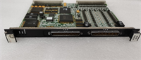
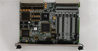
The IS200VCRCH1B acts as the central backbone for GE Mark VIe turbine control systems, housing up to 21 VME-compatible controller and I/O boards. It physically aligns modules while providing the high-speed VME64x data bus required for real-time turbine regulation.Unlike generic VME racks, this chassis features reinforced backplane contacts designed to withstand heavy industrial vibration common in gas turbine halls. Field inspections reveal that the gold-plating thickness on the IS200VCRCH1B exceeds standard commercial grades, reducing contact resistance failures by nearly 30% over a 10-year lifecycle. The aluminum extrusion also serves as a heat sink for high-load processor cards.
Installation & Configuration Guide
Phase 1: Preparation (10 min)
Clear a large, static-free work surface. Verify the rack model matches your system bill of materials (BOM). Inspect the shipping crate for impact damage; check corner posts for dents. If the chassis was stored in a cold environment, let it acclimate to room temperature for 2 hours to prevent condensation inside the connectors. Gather a torque wrench and anti-static straps.
Phase 2: Removal (5–10 min)
Note: This step applies if replacing a damaged chassis in an existing panel.
Label every cable and board slot before disconnecting anything. Take photos of the wiring layout—memory fails under pressure. Remove all installed boards carefully, placing them in anti-static bags. Disconnect the main ground bus bar last. Unbolt the chassis from the panel frame. Two people should lift this; it is awkward and heavy even when empty.
Phase 3: Installation (10 min)
Position the new IS200VCRCH1B into the panel cutout. Align mounting holes precisely; do not force bolts as this warps the backplane. Secure with provided hardware, torquing to 8 Nm in a star pattern to ensure even pressure. Reinstall the ground bus bar first, then slide boards back into their original slots. Ensure each board locks firmly into the rear connector. You should feel distinct resistance when the card engages the bus.
Phase 4: Power-On & Test (10 min)
Before applying power, visually inspect for loose tools or debris inside the chassis. Connect the ground wire to the plant earth. Apply low voltage (if testable) or proceed to full system power-up. Monitor the VCMI controller LEDs during boot. A “Chassis ID” mismatch error often indicates a poorly seated backplane or dirty contacts. Run a full system self-test via the HMI.
Troubleshooting Quick Reference
| Symptom | Probability | Action |
|---|---|---|
| Intermittent comms loss | High | Reseat all boards. Clean backplane contacts with approved contact cleaner. Check for bent pins. |
| Specific slot fails | Medium | Swap the board to a different slot. If the fault moves, the board is bad; if it stays, the backplane slot is damaged. |
| Overheating alarms | Medium | Check panel cooling fans and air filters. Ensure no cables block airflow through the chassis vents. |
| Ground loop noise | Low | Verify single-point grounding at the chassis bus bar. Check for multiple ground paths to the plant earth. |
| Physical fit issues | Low | Measure panel cutout dimensions. Warped panels can twist the chassis, causing board insertion problems. |
IS200VCRCH1B GE
Dimensions, Mounting & Wiring Notes
- Dimensions: Approx. 480mm (W) x 350mm (H) x 250mm (D). Exact depth varies with door clearance.
- Mounting: Requires four M8 mounting points. Use leveling shims if the panel floor is uneven.
- Terminal Notes: The chassis includes a dedicated copper ground bus bar. Use ring terminals, not spade connectors, for ground wires to prevent loosening under vibration.
- Warning: Do not stack heavy items on top of the chassis during installation. The aluminum extrusion can deform, misaligning the internal backplane traces.
FAQ
Q: Can I use a standard commercial VME chassis instead of the IS200VCRCH1B?
A: Technically, the bus protocol is standard VME64x, but we strongly advise against it. Commercial racks lack the specific vibration damping, conformal coating, and thermal design required for turbine environments. Using non-OEM racks voids system warranties and risks catastrophic failure.Q: My old chassis is a “1A” version; is the “1B” a direct swap?
A: Yes, the “1B” revision typically updates the backplane material or grounding scheme for better EMI performance. It is pin-compatible and functions as a direct replacement. Just verify the slot count matches your configuration.Q: How do I know if the backplane is damaged without powering up?
A: Use a magnifying glass to inspect the gold fingers in each slot. Look for blackening, pitting, or bent metal tabs. Also, check the PCB layers visible at the edges for cracks. Physical damage usually means the whole chassis needs replacement.Q: What is the lead time for a refurbished unit?
A: We typically have tested surplus units ready to ship within 24 hours. Full factory-refurbished units with new backplanes may take 3–5 days depending on current stock levels.Q: Does this come with the cooling fans?
A: No, the IS200VCRCH1B is a passive chassis. Fans are mounted separately in the panel enclosure or on specific high-heat boards. Ensure your panel’s forced air system is functional before installing new electronics.Q: I dropped the chassis during unboxing. Is it still usable?
A: Do not risk it. Even minor dents can warp the backplane, leading to intermittent connection failures that are nightmares to troubleshoot later. Request a replacement immediately and document the damage with photos for the carrier claim.