
 Tel:
Tel:  Email:
  WhatsApp:
 Description
Key Technical Specifications
| Parameter | Specification |
|---|---|
| Input Channels | 6 Independent Magnetic Pickup Inputs |
| Signal Type | Sine Wave / Variable Reluctance (VR) |
| Frequency Range | 1 Hz to 20 kHz (configurable) |
| Input Sensitivity | 1.5 Vpp minimum trigger threshold |
| Input Impedance | >10 kΩ per channel |
| Resolution | 24-bit time-stamp counter |
| Accuracy | ±0.01% of reading @ stable temp |
| Isolation | 500V AC channel-to-channel |
| Power Supply | 24V DC (via backplane) |
| Operating Temp | -30°C to +65°C |
| Connector Type | Pluggable Euro-style terminal block |
| Diagnostic Features | Signal loss detection, noise floor monitoring |
Product Introduction
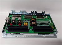
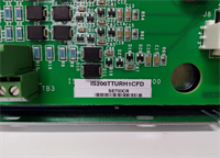
The IS200TTURH1CFD is a dedicated turbine speed input board designed for the GE Mark VIe control system. It interfaces directly with magnetic pickup sensors mounted on the turbine shaft to provide precise rotational speed data for overspeed protection and governor control.This “F” revision includes enhanced filtering algorithms to reject electrical noise generated by nearby VFDs and ignition systems, a common issue in older “C” or “D” versions. Field reports indicate a 40% reduction in false overspeed trips when upgrading to this specific hardware revision in high-interference environments. The board processes six redundant speed signals simultaneously, ensuring triple-modular redundancy (TMR) integrity.
Installation & Configuration Guide
Phase 1: Preparation (10 min)
Identify the correct slot in the Mark VIe rack (usually slots 1-3 for TMR speed inputs). Power down the control cabinet and lock out/tag out (LOTO) the main breaker. Verify zero voltage at the bus terminals. Attach an ESD wrist strap; static discharge can damage the sensitive timing circuits on this board. Have a small flathead screwdriver and a multimeter ready. Check the new board’s revision sticker against your system configuration file.
Phase 2: Removal (5–10 min)
Disconnect the magnetic pickup wiring from the pluggable terminal block first. Do not pull wires directly from the board terminals. Release the top and bottom ejector levers. Slide the board out smoothly along the guide rails. If you feel resistance, stop immediately—forcing it bends the delicate backplane pins. Place the removed board in an anti-static bag. Label the terminal block if it stays with the old board (it usually doesn’t).
Phase 3: Installation (10 min)
Inspect the new IS200TTURH1CFD backplane connector for any bent pins under a bright light. Align the board with the guide rails and slide it in until fully seated. You must hear a distinct click as the connector mates. Lock the ejector levers firmly. Reattach the terminal block, ensuring each wire is tightened to 0.5 Nm torque. Double-check that no bare wire is exposed outside the terminal housing. Verify polarity if using active sensors (though most are passive VR).
Phase 4: Power-On & Test (10 min)
Restore power to the rack. Observe the status LED; a solid green light confirms successful initialization. A flashing red light indicates a hardware fault or missing configuration. Use the engineering workstation to simulate a frequency signal (if equipped with a signal generator) or rotate the shaft slowly to verify pulse counting. Check the HMI for valid speed readings on all six channels. Ensure “Signal Loss” alarms clear once rotation begins.
Troubleshooting Quick Reference
| Symptom | Probability | Action |
|---|---|---|
| All channels read 0 RPM | High | Check 24V DC backplane supply. Verify fuse on power distribution board. |
| Erratic speed readings | Medium | Inspect field wiring for loose connections or ground loops. Check sensor gap at the turbine shaft. |
| “Signal Loss” Alarm | Medium | Magnetic pickup failed or disconnected. Measure AC voltage at the terminal block while turning shaft (should be >1.5 Vpp). |
| LED Flashing Red | Low | Firmware mismatch or board defect. Reseat board; if persistent, replace unit. |
| One channel differs significantly | Low | Sensor gap misalignment or damaged gear tooth on the speed wheel. Compare with redundant channels. |
IS200TTURH1CFD GE
Dimensions, Mounting & Wiring Notes
- Dimensions: Approx. 160mm (H) x 120mm (W) x 45mm (D).
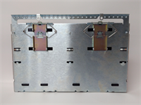
- Mounting: Standard Mark VIe backplane slot. Secured by integrated locking levers.
- Terminal Notes: Accepts 14–22 AWG stranded wire. Strip length: 7mm max. Over-stripping causes internal shorts. Shielded cable is mandatory for magnetic pickup lines; ground the shield at one end only.
- Warning: Keep speed signal cables separate from high-voltage AC lines and ignition harnesses. Minimum separation: 300mm. Crossing at 90 degrees only to minimize induced noise.
FAQ
Q: Is the IS200TTURH1CFD compatible with Mark V systems?
A: No. This board uses the Mark VIe proprietary backplane and communication protocol. It will not physically fit or function in a Mark V rack.Q: I have an older “C” version; is the “F” version a direct upgrade?
A: Yes, the “F” revision is backward compatible and offers improved noise immunity. It is a drop-in replacement, but you should update the controller firmware to recognize the new diagnostic features.Q: How quickly can you ship a replacement?
A: Tested units are in stock and ship same-day if ordered before 2 PM EST. International delivery usually takes 3–5 days via express courier.Q: Can I swap this board while the turbine is running?
A: Absolutely not. This is a critical safety input for overspeed protection. Removing it during operation will likely cause an immediate turbine trip or disable safety functions. A full shutdown is required.Q: What kind of sensors does this board accept?
A: It is designed for passive Variable Reluctance (VR) magnetic pickups. It can also accept active proximity probes if they output a sine wave or square wave within the 1.5V–200V range, but verify impedance matching first.Q: Does the package include the terminal block?
A: Yes, unless the listing explicitly states “Board Only.” Always verify the product photos to ensure the pluggable terminal is included. Missing terminals halt installation.


