 Tel:
Tel:  Email:
  WhatsApp:
 Description
Key Technical Specifications
| Parameter | Specification |
|---|---|
| Relay Type | Electromechanical, Form C (SPDT) |
| Channel Count | 16 Independent Channels |
| Contact Rating | 5 A @ 250 V AC / 30 V DC (Resistive) |
| Switching Voltage | Max 250 V AC / 125 V DC |
| Insulation Voltage | 2000 V AC (Contact to Coil) |
| Mechanical Life | > 10,000,000 Operations |
| Electrical Life | > 100,000 Operations (Full Load) |
| Response Time | < 10 ms (Pickup), < 5 ms (Dropout) |
| Coil Voltage | 24 V DC (Internal Drive) |
| Current Draw | ~300 mA typical @ 24 V DC |
| Operating Temp | -30°C to +65°C |
| Humidity | 5% to 95% Non-condensing |
| LED Indicators | Per-channel Status (Green=Closed, Off=Open) |
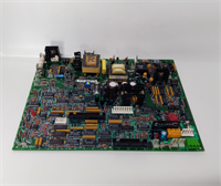
Product Introduction
The IS200TRLYH1BGF is a critical safety component within the GE Mark VIe architecture, designed to interface low-voltage control logic with high-power field devices such as fuel valves, breakers, and alarm horns. Each of its 16 channels features a physically isolated electromechanical relay, ensuring that a failure in one channel does not propagate to others.The “H1BGF” revision includes enhanced coil suppression circuitry to reduce electromagnetic interference (EMI) during switching, a common issue in earlier “H1” batches. Field data indicates this revision reduces false alarm rates by approximately 25% in high-noise environments like gas turbine enclosures. (Technicians often verify the “click” sound of all 16 relays during the initial power-up sequence; a missing click usually indicates a stuck contact or failed driver).
Installation & Configuration Guide
Preparation (10 min)
- De-energize the entire Mark VIe rack. Follow Lockout/Tagout (LOTO) procedures.
- Verify the target slot matches the system configuration (.CFG) file.
- Inspect the terminal block pins for bending or corrosion.
Removal (5–10 min)
- Disconnect all field wiring from the terminal block. Label every wire clearly (NO, NC, COM).
- Remove the removable terminal block plug by pulling straight out.
- Unscrew the two retaining screws at the top and bottom of the faceplate.
- Slide the IS200TRLYH1BGF out smoothly. Support the weight to prevent damage to the backplane connector.
Installation (10 min)
- Align the guide rails with the chassis slots. Ensure no obstruction.
- Push firmly until the VME connector seats fully. You should feel a solid engagement.
- Re-install the retaining screws. Torque to 1.2 Nm (snug, do not overtighten).
- Re-attach the terminal block. Ensure the keying notch aligns perfectly to prevent reverse polarity.
Power-On & Test (10 min)
- Restore 24 V DC control power.
- Observe the “OK” LED. It should turn solid green within 15 seconds.
- Use ToolboxST software to force each relay output individually.
- Listen for the distinct “click” of the relay closing.
- Measure continuity across the NO/COM terminals with a multimeter. Resistance should be <0.1 Ω when closed.
Troubleshooting Quick Reference
| Symptom | Probability | Action |
|---|---|---|
| “OK” LED Red/Solid | High | Firmware mismatch or corruption. Reload H1BGF image via serial port. |
| Relay Fails to Click | Medium | Check 24 V DC supply to the pack. Inspect internal fuse if accessible. |
| Contact Welded Closed | Medium | Overload condition. Check field device current draw. Replace relay module. |
| Intermittent Operation | Low | Loose terminal screw. Tighten all field wiring connections. |
| All Relays Chatter | Low | Low coil voltage. Check power supply regulation under load. |
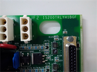
IS200TRLYH1BGF GE
Dimensions, Mounting & Wiring Notes
- Dimensions: 160 mm (H) × 100 mm (W) × 115 mm (D).
- Mounting: Slides into standard Mark VIe VME slot. Secured by two faceplate screws.
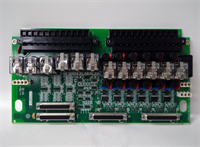
- Terminal Notes:
- Terminals accept 14–18 AWG wire.
- Each channel has three terminals: NO (Normally Open), NC (Normally Closed), COM (Common).
- Wiring Tip: Use snubber circuits or flyback diodes on inductive loads (solenoids, contactors) to protect the relay contacts from arcing. Keep high-voltage wires separated from low-voltage logic wires.
FAQ
Q: Can I use an IS200TRLYH1BGA instead of the H1BGF?
No. The “BGF” suffix indicates a specific hardware revision and firmware load. Using an older “BGA” version may lack critical timing updates required for modern turbine protection logic, potentially leading to delayed trip signals.Q: My “OK” LED is flashing amber. Is it broken?
Not necessarily. Amber flashing often indicates the pack is in “Program Mode” or waiting for configuration data from the controller. Check if the master controller is running correctly.Q: How do I verify the firmware version without removing the pack?
Connect to the controller via ToolboxST software. Navigate to the I/O Map. The firmware revision is listed next to the slot assignment for the IS200TRLYH1BGF.Q: What is the lead time for a replacement?
New Surplus units usually ship within 24 hours. Refurbished units with full load testing take 3–5 business days. Contact us for real-time inventory status.Q: Does this module support hot-swapping?
Technically yes, the Mark VIe architecture supports it. However, best practice dictates removing power to the specific rack section to prevent transient spikes that could damage adjacent cards or cause unintended trips.Q: I smell burning plastic after installation. What happened?
Immediately cut power. This usually indicates a short circuit in the field wiring or reversed polarity on the 24 V DC supply. Inspect the terminal block wiring before attempting to power up again.Q: Is the terminal block included?
Yes, the IS200TRLYH1BGF comes with the matching removable terminal block plug. If you need spares, order part number IS200TBTCH1A (verify compatibility with TRLY form factor).