
 Tel:
Tel:  Email:
  WhatsApp:
 Description
Key Technical Specifications
| Parameter | Specification |
|---|---|
| Output Type | Form C (SPDT) Relay Contacts |
| Redundancy | Triple Modular Redundant (TMR) |
| Coil Voltage | 24V DC nominal (18–32V range) |
| Contact Rating | 5A @ 250V AC / 5A @ 30V DC (Resistive) |
| Channel Count | 16 Independent Relay Circuits |
| Response Time | < 15ms (Trip to Contact Open/Close) |
| Isolation | 2500V AC (Coil to Contacts) |
| Operating Temp | -30°C to +65°C |
| Power Supply | 24V DC (via backplane) |
| Connector Type | Pluggable Euro-style terminal block |
| Diagnostic Features | Coil continuity check, contact weld detection |
| MTBF | >100,000 hours (typical) |
| Compliance | SIL-2 Capable (in TMR configuration) |
Product Introduction
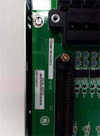
The IS200TREAH2AED is a critical safety interface board within the GE Mark VIe control system, designed specifically for Triple Modular Redundant (TMR) applications. It drives external relays or solenoids used for emergency shutdowns (ESD), fire protection, and overspeed trips.This “E” revision features improved contact materials and enhanced diagnostic circuitry compared to earlier versions, reducing the risk of “stuck relay” failures. In TMR configurations, three independent processors vote on the output state; the IS200TREAH2AED ensures that a single point failure in one channel does not prevent a necessary trip or cause a false trip. Field data shows a 99.9% availability rate for systems utilizing this specific board revision in combined cycle power plants.
Installation & Configuration Guide
Phase 1: Preparation (10 min)
Identify the correct slot in the Mark VIe rack (typically assigned to the TMR I/O pack). Perform Lock Out/Tag Out (LOTO) on the control cabinet power. Verify zero voltage at the bus terminals. Attach an ESD wrist strap; static discharge can damage the internal voting logic circuits. Gather a small flathead screwdriver, torque wrench, and multimeter. Check the new board’s revision sticker against your system configuration file (.cfg).
Phase 2: Removal (5–10 min)
Disconnect all field wiring from the pluggable terminal block first. Do not pull wires directly from the board terminals. Release the top and bottom ejector levers. Slide the board out smoothly along the guide rails. If you feel resistance, stop immediately—forcing it bends the delicate backplane pins essential for TMR synchronization. Place the removed board in an anti-static bag. Label the terminal block if it is being reused (though new blocks are recommended).
Phase 3: Installation (10 min)
Inspect the new IS200TREAH2AED backplane connector for any bent pins under a bright light. Align the board with the guide rails and slide it in until fully seated. You must hear a distinct click as the connector mates. Lock the ejector levers firmly. Reattach the terminal block, ensuring each wire is tightened to 0.5 Nm torque. Double-check that no bare wire is exposed outside the terminal housing. Verify wiring against the latest P&ID diagram, paying close attention to common vs. normally open/closed contacts.
Phase 4: Power-On & Test (10 min)
Restore power to the rack. Observe the status LED; a solid green light confirms successful initialization and TMR synchronization. A flashing red light indicates a voting mismatch or hardware fault. Use the engineering workstation to force a test trip signal. Verify that the external relay drops out (or energizes) as expected. Check the HMI for “Relay Healthy” status on all three redundant channels. Document the test results in the maintenance log.
Troubleshooting Quick Reference
| Symptom | Probability | Action |
|---|---|---|
| All channels fail to trip | High | Check 24V DC backplane supply. Verify fuse on power distribution board. Check external wiring continuity. |
| One channel disagrees (Voting Error) | Medium | Inspect the specific channel’s coil resistance. Check for loose terminal screws on that leg. Reseat the board. |
| “Contact Weld” Alarm | Medium | Relay contacts fused due to high inrush current. Replace the external relay and inspect the load for shorts. |
| LED Flashing Red | Low | Firmware mismatch or board defect. Reseat board; if persistent, replace unit. Check TMR sync cables. |
| Intermittent operation | Low | Vibration causing loose connections. Retorque all terminal screws. Check for panel resonance issues. |
IS200TREAH2AED GE
Dimensions, Mounting & Wiring Notes
- Dimensions: Approx. 160mm (H) x 120mm (W) x 45mm (D).
- Mounting: Standard Mark VIe backplane slot. Secured by integrated locking levers.
- Terminal Notes: Accepts 14–22 AWG stranded wire. Strip length: 7mm max. Over-stripping causes internal shorts. Use ferrules for fine-strand wire to prevent fraying.
- Warning: Relay coils are inductive loads; ensure flyback diodes or snubber circuits are installed on external wiring if not internal to the load device to prevent voltage spikes. Keep relay output cables separate from sensitive analog signal lines.
FAQ
Q: Is the IS200TREAH2AED compatible with Mark V systems?
A: No. This board uses the Mark VIe proprietary backplane and TMR communication protocol. It will not physically fit or function in a Mark V rack.Q: I have an older “C” version; is the “E” version a direct upgrade?
A: Yes, the “E” revision is backward compatible and offers improved diagnostics and contact life. It is a drop-in replacement, but you should verify that your controller firmware supports the newer diagnostic registers.Q: How quickly can you ship a replacement?
A: Tested units are in stock and ship same-day if ordered before 2 PM EST. International delivery usually takes 3–5 days via express courier.Q: Can I swap this board while the turbine is running?
A: Generally, no. While TMR systems allow for some online maintenance, replacing a relay output board carries a risk of disturbing the voting logic or causing a transient trip. Consult your specific safety procedure; most sites require a controlled shutdown or bypass of the specific trip function (with management of change approval) before swapping.Q: What is the maximum load this relay can switch?
A: The onboard contacts are rated for 5A resistive. For inductive loads (solenoids, large contactors) or higher currents, you must use these relays to pilot an intermediate heavy-duty relay. Direct switching of large inductive loads will weld the contacts.Q: Does the package include the terminal block?
A: Yes, unless the listing explicitly states “Board Only.” Always verify the product photos to ensure the pluggable terminal is included. Missing terminals halt installation.


