 Tel:
Tel:  Email:
  WhatsApp:
 Description
Key Technical Specifications
| Parameter | Specification |
|---|---|
| Input Type | Magnetic Pickup (MPU) or Proximity Probe |
| Channels | 3 Independent Inputs (for TMR voting) |
| Logic Architecture | Triple Modular Redundant (TMR) |
| Trip Accuracy | ±0.1% of setpoint |
| Response Time | < 10 ms (from detection to relay drop-out) |
| Frequency Range | 1 Hz to 20 kHz (configurable) |
| Mounting Type | Mark VIe Backplane Slot (Usually in PPRO/TURB rack) |
| Operating Temp | -30°C to +65°C |
| Indicator LEDs | Channel Status, Vote Status, Trip Active, Fault |
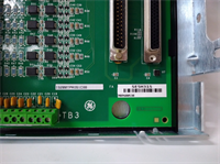
| Connector Type | High-density D-Sub or Terminal Block (Verify physical unit) |
| Isolation | Galvanic isolation between channels |
| Compliance | IEC 61508 SIL 3 capable (System dependent) |
Product Introduction
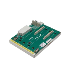
The IS200TPROS1CBB serves as the dedicated hardware guardian within the GE Mark VIe system, specifically engineered to detect turbine overspeed conditions and initiate an immediate emergency shutdown independent of the main control processor. It utilizes Triple Modular Redundant (TMR) logic to compare three separate speed signals, ensuring a trip occurs only when a genuine overspeed event is confirmed by at least two channels (2-out-of-3 voting).This card distinguishes itself through its deterministic response time and immunity to single-channel failures, preventing both nuisance trips and failure-to-trip scenarios. Field data indicates that proper shielding of the MPU inputs on this card reduces false overspeed alarms caused by electrical noise by over 90%. (Always verify the “C” revision compatibility with your existing TPRO firmware; mismatched revisions can cause voting logic errors).
Installation & Configuration Guide
Preparation (15 min)
- CRITICAL: Ensure the turbine is stopped and the protection system is bypassed or in maintenance mode per site safety procedures.
- Verify the IS200TPROS1CBB hardware revision matches the site’s Safety Instrumented System (SIS) design specification.
- Gather tools: #2 Phillips screwdriver, torque wrench, multimeter, frequency generator (for testing), ESD strap.
Removal (5–10 min)
- Disconnect the speed sensor cables (MPU 1, 2, and 3) from the front connector. Label them clearly (Channel A, B, C).
- Remove the two mounting screws securing the card to the rack.
- Gently pull the module straight out. Do not rock; backplane pins carry critical vote data.
- Real-world detail: Inspect the connector pins for oxidation. If the turbine is in a humid environment, clean with contact spray before installing the new unit.
Installation (10 min)
- Align the IS200TPROS1CBB with the designated TPRO slot (often slot 1, 2, or 3 in the protection rack).
- Push firmly until the backplane connector seats fully.
- Secure mounting screws. Torque to 1.5 Nm.
- Reconnect speed sensor cables. Ensure shields are grounded at the cabinet entry point, not at the card, unless specified otherwise.
Power-On & Test (20 min)
- Restore control power. Observe LEDs: All three channel status lights should be green.
- Use a frequency generator to simulate speed signals on each channel individually.
- Verify that the card does not trip when one channel shows overspeed (1-out-of-3 should pass).
- Simulate overspeed on two channels simultaneously; verify the Trip Relay drops out immediately.
- Download/Verify the configuration using the Mark VIe Toolbox (Protection Configurator).
Troubleshooting Quick Reference
| Symptom | Probability | Action |
|---|---|---|
| Red “Fault” LED | High | Check input wiring continuity. A broken MPU cable often triggers a channel fault. |
| Nuisance Trips | Medium | Check for electrical noise on speed lines. Verify grounding scheme. Check for loose connections. |
| No Trip on Test | High | DANGER: Verify test procedure. Check if the “Force” or “Bypass” mode is active. Confirm voting logic settings. |
| One Channel Dead | Medium | Swap the input cable to a different channel on the card to isolate card vs. sensor fault. |
| Communication Loss | Low | Reseat the card. Check backplane voltage. Verify TMR network integrity. |
IS200TPROS1CBB GE
Dimensions, Mounting & Wiring Notes
- Dimensions: Approx. 160mm (H) x 120mm (W) x 45mm (D) — Verify with physical caliper measurement.
- Mounting: Standard Mark VIe backplane slot (Protection Rack).
- Terminal Notes: Use shielded twisted pair cable (18–22 AWG) for all speed inputs.
- Clearance: Maintain 50mm clearance for airflow and probe access.
- Warning: Never bypass the TPRO card inputs with a jumper wire during operation. This defeats the safety system.
FAQ
Q: Is the IS200TPROS1CBB compatible with Simplex systems?
A: The hardware can often be configured for Simplex, but it is designed and priced for TMR applications. You must change the software configuration to match the physical architecture, or it will fault.Q: What is the difference between “CBB” and “BAA” revisions?
A: The “C” revision typically includes updated FPGA logic or component obsolescence updates. While physically interchangeable, the firmware configuration file must match the hardware revision exactly.Q: Can I test this card without spinning the turbine?
A: Yes. You must use a calibrated frequency signal generator to inject simulated speed signals into the MPU inputs. This is standard practice during commissioning and outages.Q: Why are there three LEDs for speed input?
A: Each LED represents one of the three independent speed channels. In a healthy TMR system, all three should track the same speed. If one diverges, it indicates a sensor or wiring issue.Q: Does this card require a separate power supply?
A: No, it draws power from the Mark VIe backplane. However, the speed sensors (MPUs) may require external power or generate their own signal depending on the type (active vs. passive).Q: How often must this be proof-tested?
A: Per IEC 61511 standards for SIL 3 systems, a full proof test (simulating trip conditions) is typically required every 1 to 2 years, depending on your site’s Safety Requirement Specification (SRS).