 Tel:
Tel:  Email:
  WhatsApp:
 Description
Key Technical Specifications
| Parameter | Specification |
|---|---|
| Connector Type | 40-pin or 60-pin Ribbon Cable Interface (Back) |
| Field Terminals | Removable Screw Terminal Blocks (3-wire per point) |
| Wire Gauge | 14–22 AWG (Stranded or Solid) |
| Torque Rating | 0.5 – 0.7 Nm (4.4 – 6.2 in-lbs) |
| Voltage Rating | 300 V AC/DC (Terminal to Ground) |
| Current Rating | 10 A per terminal (Max continuous) |
| Grounding | Dedicated shield drain bar with low-impedance path |
| Mounting | DIN Rail or Direct Backplane Mount |
| Operating Temp | -40°C to +70°C |
| Material | Flame-retardant Polyamide (UL94 V-0) |
| Revision Code | H6ACD (Specific Trace Layout) |
| Dimensions | Approx. 280 mm (W) × 120 mm (H) × 60 mm (D) |
Product Introduction
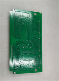
The IS200TDBTH6ACD serves as the critical bridge between the harsh field environment and the sensitive electronics of the GE Mark VIe control system. It routes discrete inputs, discrete outputs, and analog signals from the turbine sensors and actuators to the corresponding I/O packs via high-quality ribbon cables.The “H6ACD” revision features an optimized ground plane layout designed to minimize electromagnetic interference (EMI), a common challenge in gas turbine generator halls. Compared to earlier “H4” or “H5” versions, this board includes enhanced shielding termination points that reduce noise injection by up to 30%. Field technicians appreciate the color-coded terminal labels printed directly on the board, which significantly reduces wiring errors during commissioning or maintenance outages.
Installation & Configuration Guide
Preparation (10 min)
- Ensure the Mark VIe rack is de-energized and locked out (LOTO).
- Verify the IS200TDBTH6ACD matches the slot assignment in the electrical schematic.
- Inspect the ribbon cable connector pins on the back of the board for any bending.
Removal (5–10 min)
- Label all field wires before disconnecting. Use permanent markers or pre-printed tags.
- Loosen terminal screws and remove field wires.
- If connected to an I/O pack, carefully unplug the ribbon cable from the rear of the terminal board.
- Unbolt the terminal board from the DIN rail or mounting plate.
Installation (10 min)
- Mount the IS200TDBTH6ACD securely on the DIN rail. Ensure it sits flat without stress.
- Connect the ribbon cable to the I/O pack first, then plug the other end into the terminal board. Ensure the red stripe on the cable aligns with Pin 1.
- Re-connect field wiring according to the loop diagram. Tighten screws to 0.6 Nm.
- Connect the cable shield drains to the dedicated grounding bar on the board. Do not leave shields floating.
Power-On & Test (10 min)
- Visually inspect all connections for loose strands or crossed wires.
- Perform a continuity check (Ohms) from the field terminal to the I/O pack pin (if accessible) before applying power.
- Restore control power.
- Verify signal integrity using ToolboxST software. Check for noisy analog readings or erratic discrete status changes.
Troubleshooting Quick Reference
| Symptom | Probability | Action |
|---|---|---|
| Signal Noise on Analog Channels | High | Check shield grounding. Ensure shields are terminated at the TDBT ground bar, not just at the sensor. |
| Intermittent Discrete Input | Medium | Loose terminal screw. Re-torque all connections on the affected channel. |
| No Communication to I/O Pack | Medium | Ribbon cable misaligned or damaged. Reseat the cable; check for broken conductors. |
| Burnt Terminal Smell | Low | Overcurrent or short circuit. Check field device load against the 10A rating. Inspect for carbon tracking. |
| Corrosion on Terminals | Low | High humidity ingress. Check cabinet seals. Clean contacts with electrical contact cleaner. |
IS200TDBTH6ACD GE
Dimensions, Mounting & Wiring Notes
- Dimensions: 280 mm (W) × 120 mm (H) × 60 mm (D).
- Mounting: Standard 35mm DIN Rail. Includes mounting clips.
- Terminal Notes:
- Accepts ring lugs or fork lugs (max width 6mm).
- Strip length: 8–10 mm for bare wire insertion.
- Wiring Tip: Always route power and signal wires in separate conduits until they reach the terminal board. Crossing high-voltage AC lines over the IS200TDBTH6ACD ribbon cable can induce significant noise.
FAQ
Q: Is the IS200TDBTH6ACD compatible with older H4 I/O packs?
Mechanically, yes. However, the pinout mapping might differ. You must cross-reference the “H6ACD” wiring diagram with your specific I/O pack manual. Mismatched pinouts can send 24V DC into a 5V logic input, destroying the pack.Q: Can I reuse the old ribbon cable from an H5 board?
Yes, provided the cable is undamaged and the connector keying matches. However, if the old cable shows signs of brittleness or insulation cracking (common in high-heat environments), replace it with a new shielded ribbon cable.Q: What is the difference between TDBT and TCTL boards?
TDBT (Terminal Board Discrete) is generally used for standard I/O signals. TCTL boards often include additional circuitry like fuses or specific filtering. Check your BOM to ensure you aren’t substituting a passive board for an active one.Q: How do I identify Pin 1 on the ribbon connector?
Look for the small triangle or “1” molded into the plastic housing near the connector. The red stripe on the ribbon cable must align with this mark.Q: My analog readings are drifting. Is it the terminal board?
Possibly, if the ground connection is corroded. More likely, it is a sensor issue or EMI. First, tighten the ground bar screws on the IS200TDBTH6ACD and verify the shield continuity.Q: Does this board come with the terminal block plugs?
Yes, the IS200TDBTH6ACD typically ships with the removable terminal block plugs installed. If you need extra plugs for quick disconnects during testing, order the specific accessory part number listed in the GE manual.Q: What is the warranty on this passive component?
Standard warranty is 1 year. Since there are no active electronics, failures are usually due to manufacturing defects in the traces or connector molding, which are fully covered.