 Tel:
Tel:  Email:
  WhatsApp:
 Description
Key Technical Specifications
| Parameter | Specification |
|---|---|
| Input Type | Dry Contact (Switch Closure) |
| Channels | 24 Independent Inputs |
| Wetting Voltage | 24V DC (Provided by the board or external, configurable) |
| Input Current | Approx. 3–5 mA per channel (when closed) |
| Logic Levels | Open = Logic 0, Closed = Logic 1 (Configurable) |
| Mounting Type | Mark VIe Backplane Slot |
| Operating Temp | -30°C to +65°C |
| Indicator LEDs | Per-channel status (On = Contact Closed) |
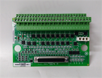
| Connector Type | 3-tier Euro-style terminal blocks (Removable) |
| Isolation | Optical isolation between field and backplane (Channel groups) |
| Wire Gauge | 18–12 AWG (Stranded) |
| Weight | Approx. 1.1 kg |
| Compliance | CE, UL, CSA |
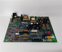
Product Introduction
The IS200STCIH6AED acts as the primary interface for discrete status signals within the GE Mark VIe simplex control architecture, converting mechanical switch closures into digital logic states for the main processor. It is widely used for monitoring valve limit switches, pressure safety switches, and auxiliary motor status.This board features individual LED indicators for every channel, allowing technicians to instantly visualize the state of 24 different field devices without needing a laptop. The “H6” revision typically includes improved noise filtering and updated optical isolators compared to earlier “H1” versions, reducing susceptibility to electrical transients common in power plant environments. (Crucial: Verify if your system uses internal 24V wetting or external power; misconfiguration here is the #1 cause of input failures).
Installation & Configuration Guide
Preparation (10 min)
- Execute Lockout/Tagout (LOTO) on the control power feeding the rack.
- Verify the slot assignment in the Mark VIe Toolbox configuration matches the physical installation.
- Prepare tools: #2 Phillips screwdriver, wire strippers, multimeter, ESD strap.
Removal (5–10 min)
- Disconnect all field wiring from the three tiers of terminal blocks. Label every wire corresponding to its terminal number (e.g., TB1-1, TB1-2).
- Remove the two mounting screws securing the board to the rack.
- Pull the module straight out from the backplane.
- Real-world detail: Check the terminal blocks for cracked plastic or burnt pins, which can happen if a short circuit occurred in the field wiring.
Installation (10 min)
- Align the IS200STCIH6AED guides with the rack slots.
- Push firmly until the backplane connector seats fully. You should feel a distinct click.
- Reinstall mounting screws. Torque to 1.5 Nm.
- Reconnect field wiring. Ensure tightness to prevent high-resistance connections that can cause “chattering” inputs.
Power-On & Test (10 min)
- Restore control power (24V DC) to the rack.
- Verify the “Power” LED on the associated processor card is green.
- Manually close a field switch (e.g., a limit switch).
- Observe the corresponding LED on the IS200STCIH6AED; it should illuminate immediately.
- Verify the status change in the HMI or Toolbox software.
Troubleshooting Quick Reference
| Symptom | Probability | Action |
|---|---|---|
| LED On but Software reads 0 | High | Check the logic inversion setting in the configuration file. Verify backplane communication. |
| LED Off but Switch Closed | High | Measure voltage across the input terminals. If 0V, check for broken wire or blown fuse (if external power). |
| Flickering LED | Medium | “Chattering” switch or loose wire. Tighten terminal screws. Inspect field switch for wear. |
| Multiple Channels Faulty | Medium | Check the common return path or the 24V supply rail for that group of channels. |
| Board Not Recognized | Low | Reseat the board. Clean backplane pins. Verify slot ID jumpers (if applicable). |
IS200STCIH6AED GE
Dimensions, Mounting & Wiring Notes
- Dimensions: Approx. 160mm (H) x 120mm (W) x 90mm (D) — Verify with physical caliper measurement.
- Mounting: Standard Mark VIe backplane slot.
- Terminal Notes: Use stranded wire (18–12 AWG). Ferrules are mandatory for vibration zones to prevent strand breakage.
- Clearance: Maintain 75mm clearance in front for wiring access.
- Warning: Do not apply 120V AC or higher to these inputs; they are designed for 24V DC logic levels only. Doing so will destroy the optical isolators.
FAQ
Q: What is the difference between STCI and TCII?
A: STCI (Simplex Terminal Contact Input) is for non-redundant applications or where redundancy is handled by multiple cards. TCII is often used in Triple Modular Redundant (TMR) configurations with specific voting hardware. Always match the card type to your system architecture (Simplex vs. TMR).Q: Can I use this for wet contacts (voltage inputs)?
A: Yes, but you must configure the “wetting voltage” jumper or setting correctly. If the field device provides its own 24V, ensure the board is set to “dry contact” mode (passive) to avoid back-feeding voltage.Q: My LED is dim. Is the board failing?
A: Usually not. A dim LED often indicates a high-resistance connection in the field wiring or a failing field switch that isn’t making full contact. Measure the loop resistance.Q: Is the IS200STCIH6AED backward compatible with H1 versions?
A: Physically, yes. Functionally, yes. However, always verify the firmware configuration file (.cfg) matches the hardware revision to ensure proper diagnostic reporting.Q: How do I test the inputs without moving the actual valves/switches?
A: You can use a shorting bar or a piece of wire to momentarily short the input terminal to the common return terminal at the board. This simulates a switch closure.Q: Why are there three rows of terminals?
A: The three tiers allow for dense wiring of 24 channels (8 channels per tier typically), organizing the positive, negative, and shield/return connections efficiently.