
 Tel:
Tel:  Email:
  WhatsApp:
 Description
Key Technical Specifications
| Parameter | Specification |
|---|---|
| Output Type | Current Sourcing (4-20 mA) |
| Channel Count | 8 Independent Channels |
| Accuracy | ±0.1% of Full Scale (Typical) |
| Resolution | 16-bit D/A Conversion |
| Load Impedance | Max 600 Ω @ 24 V Supply |
| Update Rate | Configurable (Default 20 ms) |
| Isolation | Channel-to-Channel & Channel-to-Ground (500 V RMS) |
| Loop Power | Internal 24 V DC available per channel (jumper selectable) |
| Input Voltage | 5V DC (Backplane), 24V DC (Field Side) |
| Current Draw | ~200 mA @ 5V DC + Sum of Loop Loads |
| Operating Temp | -30°C to +65°C |
| LED Indicators | OK (Green), Fault (Red), Per-Channel Activity |
| Firmware Rev | H2AAA |
Product Introduction
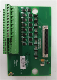
The IS200STAOH2AAA is a critical interface module within the GE Mark VIe turbine control system, designed to convert digital control signals into precise 4-20 mA analog currents. These signals typically drive final control elements such as fuel metering valves, inlet guide vane actuators, or remote chart recorders.As a “Simplex” pack, it operates as a single-channel path, meaning it does not have the inherent hardware redundancy of a “Triplicated” (TDAO) pack, making it suitable for non-critical monitoring or auxiliary control loops where a single point of failure is acceptable. The “H2AAA” revision includes improved linearization algorithms and faster fault detection compared to earlier “H1” loads. Field engineers often verify the “OK” LED status; if it flashes amber, the pack is in a “hold last value” state due to a communication loss with the controller.
Installation & Configuration Guide
Preparation (10 min)
- Download the latest configuration file (.CFG) from the engineering workstation.
- Verify the dip switches (if present on the specific sub-revision) match the loop power requirements (Internal vs. External).
- Inspect the terminal block pins for corrosion or bending.
Removal (5–10 min)
- Label all field wires (Signal+, Signal-, Shield).
- Disconnect field wiring from the terminal block.
- If the terminal block is removable, pull it straight out.
- Unscrew the two retaining screws on the faceplate.
- Slide the IS200STAOH2AAA straight out, supporting the weight to avoid backplane damage.
Installation (10 min)
- Align the guide rails with the VME chassis slot.
- Push firmly until the connector seats fully.
- Secure the faceplate screws. Torque to 1.2 Nm.
- Re-connect field wiring. Ensure shield drains are connected to the cabinet ground bar, not the module ground (unless specified).
- If using internal loop power, ensure the field device is compatible with the module’s 24V source capacity.
Power-On & Test (10 min)
- Apply rack power.
- Wait for the boot sequence (approx. 15 seconds). The “OK” LED should turn solid green.
- Use ToolboxST software to force an output value (e.g., 4 mA, 12 mA, 20 mA).
- Measure the current at the terminal block with a calibrated multimeter.
- Verify the reading matches the forced value within ±0.1 mA.
Troubleshooting Quick Reference
| Symptom | Probability | Action |
|---|---|---|
| “OK” LED Flashing Amber | High | Communication loss with controller. Check VME backplane connection and controller status. |
| Output Stuck at 0 mA | Medium | Open circuit in field wiring or blown internal fuse (if applicable). Check continuity. |
| Output Stuck at Max (>22 mA) | Medium | Short circuit in field wiring or “Fail-High” configuration active. Inspect wiring. |
| Inaccurate Reading (Offset) | Low | Calibration drift or ground loop. Check grounding scheme; re-calibrate via software. |
| Noise on Output Signal | Low | Poor shielding. Ensure cable shield is grounded at one end only (usually cabinet side). |
IS200STAOH2AAA GE
Dimensions, Mounting & Wiring Notes
- Dimensions: 160 mm (H) × 100 mm (W) × 115 mm (D).
- Mounting: Standard Mark VIe VME slot.
- Terminal Notes:
- Terminals accept 14–18 AWG wire.
- Each channel typically has two terminals: Out+ and Out-.
- Common ground terminals are provided for shield drainage.
- Wiring Tip: For long cable runs (>100m), verify the total loop resistance does not exceed the module’s drive capability (typically 600Ω). Use twisted pair shielded cable to minimize EMI pickup.
FAQ
Q: Can I replace an IS200STAOH1AAA with the H2AAA model?
Yes, in most cases. The H2AAA is a newer firmware revision that is backward compatible. However, you must update the system configuration file in ToolboxST to recognize the new revision features and ensure proper scaling.Q: What happens if I lose communication with the controller?
By default, the IS200STAOH2AAA will go to a pre-configured “Fail-Safe” state. This is usually set to “Hold Last Value,” “Zero Scale (4 mA),” or “Full Scale (20 mA)” depending on the safety requirements of the driven device. This is configured in the logic.Q: Does this module provide loop power?
Yes, the IS200STAOH2AAA can provide 24 V DC loop power internally for each channel. This is selected via software configuration or hardware jumpers (depending on the specific board layout). If the field device has its own power supply, do not enable internal power to avoid conflict.Q: How do I calibrate the outputs?
Calibration is performed digitally via the ToolboxST software. There are no physical potentiometers on the card. You can perform a “Trim” function by entering the measured values from a precision multimeter.Q: Is this module redundant?
No, the “S” in STAO stands for Simplex. It is a single-path module. For critical trip functions requiring redundancy, GE uses the TDAO (Triplicated Analog Output) architecture with three separate packs voting on the output.Q: My multimeter reads 23 mA when I command 20 mA. Is it broken?
Not necessarily. 20 mA is the nominal full scale. Many transmitters and modules allow a “over-range” up to 22-24 mA to indicate a fault or specific alarm condition. Check the configuration to see if “Alarm High” is set to >20 mA.Q: What is the warranty period?
Standard warranty is 1 year from shipment. This covers functional failures. Damage from lightning, improper grounding, or connecting high voltage to the low voltage terminals is not covered.


