 Tel:
Tel:  Email:
  WhatsApp:
 Description
Key Technical Specifications
| Parameter | Specification |
|---|---|
| Analog Inputs | 8 Channels (Configurable: 4-20mA, 0-10V, ±10V) |
| Analog Outputs | 4 Channels (4-20mA isolated) |
| Discrete I/O | 4 Channels (24V DC, configurable) |
| PID Loops | Up to 4 independent PID loops executed onboard |
| Resolution | 16-bit A/D and D/A conversion |
| Update Rate | 10ms typical for PID loop execution |
| Input Impedance | 250Ω (Current), >1MΩ (Voltage) |
| Output Load | Max 600Ω per channel |
| Isolation | 500V AC (Channel to Channel/Backplane) |
| Operating Temp | -30°C to +65°C |
| Power Supply | 24V DC (via backplane) |
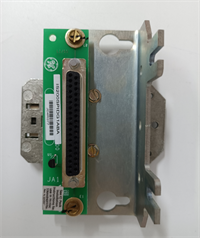
| Connector Type | Pluggable Euro-style terminal block |
| Diagnostic Features | Wire break detection, range checking, PID saturation alarm |
Product Introduction
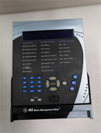
The IS200SPIDG1ABA is a specialized function board within the GE Mark VIe control system, designed to handle complex control loops locally. Unlike standard I/O boards that simply pass data to the main controller, this board contains an onboard processor capable of executing Proportional-Integral-Derivative (PID) algorithms directly.This architecture significantly reduces the load on the primary turbine controller and minimizes latency for fast-acting auxiliary loops. The “A” revision represents the initial release of this specific form factor, widely used in combined cycle plants for controlling feedwater pumps, fuel gas pressure regulators, and inlet guide vanes. Its robust design includes comprehensive diagnostics for wire breaks and sensor failures, ensuring safe fallback modes if a signal is lost.
Installation & Configuration Guide
Phase 1: Preparation (10 min)
Identify the assigned slot in the Mark VIe rack (consult the system architecture diagram; these are often placed in specific I/O packs). Perform Lock Out/Tag Out (LOTO) on the control cabinet power. Verify zero voltage. Attach an ESD wrist strap. Gather a small flathead screwdriver, torque wrench, and multimeter. Crucial: Download the latest configuration file (.cfg) and verify the PID tuning parameters (P, I, D gains) match your process requirements before powering up.
Phase 2: Removal (5–10 min)
Disconnect all field wiring (analog and discrete) from the pluggable terminal block. Do not pull wires from the board terminals. Release the top and bottom ejector levers. Slide the board out smoothly along the guide rails. If resistance is felt, stop immediately to avoid bending backplane pins. Place the removed board in an anti-static bag. Label all wires clearly if the terminal block is being reused.
Phase 3: Installation (10 min)
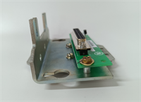
Inspect the new IS200SPIDG1ABA backplane connector for bent pins. Align the board with the guide rails and slide it in until fully seated; listen for the distinct click. Lock the ejector levers firmly. Reattach the terminal block, tightening screws to 0.5 Nm torque. Ensure no bare wire is exposed. Verify polarity for all 4-20mA loops (source vs. sink configuration) as defined in the wiring diagram.
Phase 4: Power-On & Test (10 min)
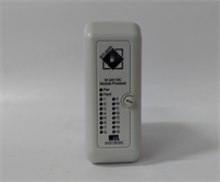
Restore power to the rack. Observe the status LED; solid green indicates successful initialization. A flashing red light suggests a configuration mismatch or hardware fault. Use the engineering workstation to monitor the raw analog input values; they should match your multimeter readings at the terminal block. Force a setpoint change in the HMI and observe the analog output response; verify the PID loop is actively correcting the error. Check for any “Wire Break” or “Bad PV” (Process Variable) alarms.
Troubleshooting Quick Reference
| Symptom | Probability | Action |
|---|---|---|
| All inputs read 0 or max | High | Check 24V DC backplane supply. Verify common ground connections. Check if the board is in “Hold” mode. |
| PID Loop not responding | Medium | Verify the loop is enabled in the configuration file. Check for “Manual” mode override. Inspect tuning constants (gains may be zeroed). |
| “Wire Break” Alarm | Medium | Measure loop resistance; look for open circuits in field wiring or failed transmitters. Verify 24V loop power is present. |
| Output saturates at 20mA | Medium | Process variable is far from setpoint, or sensor is failed low. Check sensor health. Verify PID action (Direct vs. Reverse). |
| LED Flashing Red | Low | Firmware mismatch or board defect. Reseat board; if persistent, replace unit. Verify .cfg file matches hardware revision. |
IS200SPIDG1ABA GE
Dimensions, Mounting & Wiring Notes
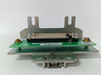
- Dimensions: Approx. 160mm (H) x 120mm (W) x 45mm (D).
- Mounting: Standard Mark VIe backplane slot. Secured by integrated locking levers.
- Terminal Notes: Accepts 14–22 AWG stranded wire. Strip length: 7mm max. Use shielded twisted pair cable for all analog signals to prevent noise interference. Ground the shield at the cabinet entry point only.
- Warning: Do not mix high-voltage AC wiring with these low-level analog signals in the same conduit. Ensure proper separation (>300mm) to prevent induced noise which can cause PID instability.
FAQ
Q: Is the IS200SPIDG1ABA compatible with Mark V systems?
A: No. This board uses the Mark VIe proprietary backplane and communication protocol. It will not physically fit or function in a Mark V rack.Q: Can I use this board for simple I/O without using the PID feature?
A: Yes. The board can be configured to act as a standard analog I/O card, passing raw data to the main controller for PID processing if preferred, though this negates the latency benefit.Q: How many PID loops can run simultaneously?
A: The board supports up to 4 independent PID loops running concurrently. Each loop can be assigned to different control variables (e.g., pressure, temperature, level, flow).Q: What happens if the board fails while controlling a critical valve?
A: The system should be configured with a “Fail-Safe” mode. Typically, the output will hold its last value, go to 0%, or go to 100% depending on the specific safety configuration defined in the logic. Redundant control strategies are recommended for critical loops.Q: Does the package include the terminal block?
A: Yes, unless the listing explicitly states “Board Only.” Always verify the product photos to ensure the pluggable terminal block is included. Missing terminals will halt installation.Q: Can I hot-swap this board?
A: Generally, no. While Mark VIe supports some online maintenance, replacing a board with active PID loops carrying live processes carries significant risk of process upset or trip. A controlled shutdown or bypass of the specific control loop (with Management of Change approval) is required.