

 Tel:
Tel:  Email:
  WhatsApp:
 Description
Product Introduction
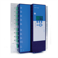
Plant engineers know the headache of trying to diagnose why a critical pump motor tripped at 2 a.m. when the old electromechanical overload relay offers zero data history. The GE INTELLIX MO150 replaces these “dumb” devices with a smart guardian that records pre-fault waveforms, tracks thermal capacity used, and logs every start attempt.We deployed these units last year to retrofit a wastewater treatment lift station where frequent voltage sags were causing nuisance trips on legacy hardware. Unlike basic overloads, the MO150 features adaptive thermal modeling that accounts for ambient temperature and cooling conditions, preventing false trips during hot summer days while still protecting the winding insulation. It integrates directly into existing Motor Control Centers (MCCs) via standard DIN rail or flush mount kits, communicating real-time amp readings to the SCADA system without needing external transducers. Honestly, the ability to remotely reset the relay after a verified cool-down period saves the maintenance crew a 30-minute drive to the site every single time.

Key Technical Specifications
| Parameter | Value |
|---|---|
| Rated Current Range | 0.5 – 150 A (Direct) or via CTs up to 6000 A |
| Voltage Rating | 100 – 690 VAC (Line Voltage) |
| Control Power | 24–240 VAC/DC (Universal) |
| Protection Functions | Overload, Underload, Phase Loss/Reversal, Ground Fault, Jam/Stall |
| Communication Ports | RS-485 (Modbus RTU), Optional Ethernet (Modbus TCP) |
| Digital Inputs | 4 Configurable (Start, Stop, Reset, Emergency) |
| Relay Outputs | 3 Form C (Trip, Alarm, Auxiliary) |
| Thermal Memory | Non-volatile (Retains heat status during power loss) |
| Harmonic Monitoring | THD Calculation for Voltage and Current |
| Operating Temperature | -20 °C to +60 °C |
| Enclosure Rating | IP20 (Panel Mount), IP65 (with optional faceplate) |
| Certifications | UL, CSA, CE, IEC 60255 |
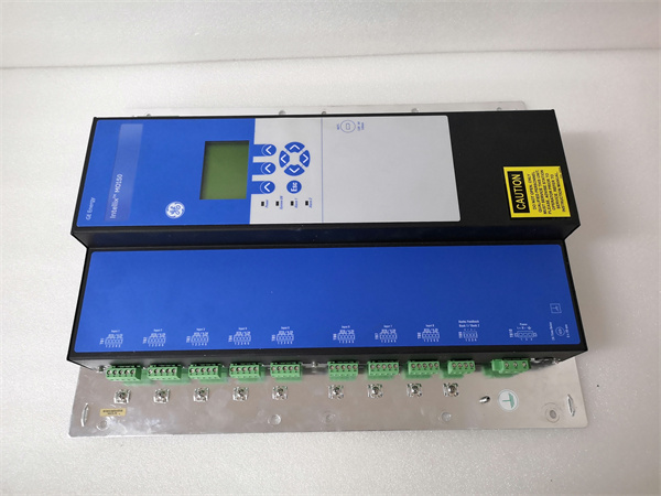
INTELLIX MO150 GE
Application Scenarios & Pain Points
The production line halted for six hours because a 50 HP fan motor locked up, but the operator didn’t know if it was a mechanical jam or an electrical fault until an electrician arrived to megger the windings. The GE INTELLIX MO150 eliminates this guesswork by distinguishing between a “Jam” (high current immediately upon start) and a “Stall” (high current during run) and logging the exact current waveform at the moment of trip. This granular data tells you instantly whether to call the mechanic or the electrical team.
- HVAC Chiller Plants: Need to prevent short-cycling on large compressors? The MO150 enforces configurable minimum off-times and tracks the number of starts per hour, extending motor life significantly.
- Mining Conveyor Belts: What if a belt snaps and the motor overspeeds? The underload protection function detects the drop in current torque and trips the breaker before the runaway motor damages the gearbox.
- Oil & Gas Pump Jacks: Harsh environments cause voltage fluctuations. The phase unbalance protection prevents the motor from overheating due to negative sequence currents, which are invisible to standard thermal overloads.
- Water/Wastewater Lift Stations: Remote sites often suffer from communication blackouts. The non-volatile thermal memory ensures that if power blips out, the relay remembers how “hot” the motor was and won’t allow a restart until it’s safe, preventing cumulative thermal damage.
Case Study:
A chemical processing plant in Texas struggled with recurring failures on their main circulation pumps. The motors would burn out every 18 months, but the protection relays never tripped, showing “normal” current levels. The reliability engineer, David, installed GE INTELLIX MO150 units and enabled the “Thermal Capacity Used” trending feature. The data revealed that while the running current was nominal, the motors were being started too frequently against a closed discharge valve, accumulating heat faster than they could dissipate it. By adjusting the start-per-hour limit in the MO150 and adding a delay timer, they eliminated the thermal stress. Motor lifespan increased from 1.5 years to over 8 years, saving an estimated $150,000 in replacement costs and downtime.Lessons Learned: Installation Pitfalls
- Firmware version mismatch — Older MO150 firmware may not support newer Modbus register maps expected by modern SCADA systems. ❗ We once spent a day troubleshooting why the “Run Hours” counter wouldn’t read, only to find the relay needed a firmware update to expose that specific register. Check the GE compatibility matrix.
- DIP switch / jumper misconfiguration — The CT ratio is often set via dip switches or software parameters. If the physical switches don’t match the software setting, the current readings will be off by a factor of 10 or 100, leading to immediate nuisance trips or failure to trip. Verify both settings match the installed CTs.
- Terminal / wiring incompatibility — The control power terminals are sometimes located next to high-voltage current inputs on compact models. Accidental cross-wiring here can fry the logic board instantly. Double-check the terminal diagram; don’t assume the layout matches the previous brand’s relay.
- Power supply undersizing — While the relay itself draws little power, if you are powering external indication lights or auxiliary coils from the relay’s auxiliary output, ensure the total load doesn’t exceed the contact rating (usually 5A). Welding contacts shut on a safety trip is a nightmare scenario.
- ESD damage — Communication ports (RS-485) are vulnerable to static and surge, especially in long cable runs across a plant floor. Without proper shielding and grounding of the comms cable, a nearby lightning strike or VFD noise burst can take out the comms chip, leaving you blind to remote data. Use shielded twisted pair and ground at one end.