 Tel:
Tel:  Email:
  WhatsApp:
 Description
Key Technical Specifications
| Parameter | Specification |
|---|---|
| Input Voltage | 48V DC (Nominal) |
| Input Range | 36V DC to 72V DC |
| Total Power | 75 Watts |
| 5V Output | 6.0 Amps (Max) |
| 24V Output | 2.0 Amps (Max) |
| Efficiency | > 85% (Typical) |
| Hold-up Time | 10ms (Min) at full load |
| Operating Temp | 0°C to 60°C (32°F to 140°F) |
| Storage Temp | -40°C to 85°C |
| Humidity | 5% to 95% (Non-condensing) |
| Mounting | Series 90-70 Backplane Slot |
| Protection | Over-current, Over-voltage, Thermal shutdown |
| Weight | Approx. 0.6 kg (1.3 lbs) |
| Dimensions | Single-slot width (Standard 90-70 form factor) |
Product Introduction
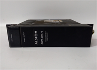
The GE IC697PWR748D is a high-voltage DC power supply designed specifically for the Series 90-70 PLC chassis. It accepts a nominal 48V DC input, common in telecommunications and utility substations, and regulates it to stable 5V and 24V rails for CPU and I/O modules.This unit delivers up to 75W of continuous power, supporting dense I/O configurations without external supplemental supplies. Field data shows stable operation even with input fluctuations between 40V and 65V DC. (Always verify your site’s DC bus stability). The “D” revision indicates updated component tolerances for improved thermal performance compared to earlier “A” or “B” versions.
Installation & Configuration Guide
Preparation (10 min)
Ensure the main 48V DC source is LOCKED OUT and TAGGED OUT. Verify the input polarity (+/-) on your terminal block. A reverse connection will destroy the module instantly. Gather a torque screwdriver (0.5–0.8 Nm range) and insulated tools. Check the chassis slot for debris or bent backplane pins.Removal (5–10 min)
Disconnect the input wiring from the front terminal block. Loosen the mounting screws securing the module to the chassis rail. Slide the unit out horizontally. If resistance is felt, check for retaining clips or adjacent module interference. Place the removed unit in an anti-static bag.Installation (10 min)
Slide the IC697PWR748D into the designated power slot (usually the leftmost or rightmost slot, depending on chassis config). Ensure the backplane connector engages fully. Tighten the mounting screws to secure the unit against vibration. Reconnect the 48V DC wires: Positive to “+”, Negative to “-“. Torque terminals to 0.6 Nm. Double-check polarity before energizing.Power-On & Test (10 min)
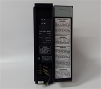
Remove lockout tags and apply 48V DC power. Observe the front LEDs immediately. The “PWR OK” LED should illuminate solid green within 2 seconds. Use a multimeter to measure the 5V and 24V outputs at the test points (if accessible) or at the nearest I/O module terminals. Values must be within ±5%. Listen for abnormal coil whine or clicking sounds.
Troubleshooting Quick Reference
| Symptom | Probability | Action |
|---|---|---|
| No LEDs lit | High | Input voltage missing or reversed. Measure 48V at terminals. Check fuse/breaker. |
| PWR LED Flashing Red | Medium | Output overload or short circuit. Disconnect loads one by one to isolate fault. |
| 5V Output Low (<4.75V) | High | Failing capacitor or excessive load. Measure total current draw; ensure <6A. |
| Module shuts down after 1 min | Medium | Thermal overload. Check chassis airflow and fan operation. Clean dust filters. |
| Intermittent faults | Low | Loose terminal screw. Retorque all input/output connections. |
Dimensions, Mounting & Wiring Notes
- Dimensions: Single-slot width (approx. 30mm W x 160mm H x 180mm D). Fits standard Series 90-70 racks.
- Mounting: Slides into backplane; secured by two front-face screws to the chassis rail.
- Terminal Notes: Input terminals accept up to 12 AWG wire. Use stranded copper wire only. Do not mix AC and DC wiring in the same conduit. Ensure the ground lug on the chassis is bonded to earth ground to prevent noise coupling.
IC697PWR748D GE
FAQ
Q: Can I use this with a 24V DC input?
A: No. The IC697PWR748D requires a minimum of 36V DC. Connecting 24V will result in no output and potential undervoltage lockout issues. You need the PWR740 series for 24V inputs.Q: My PWR748D keeps tripping. Is it broken?
A: Not necessarily. It often indicates a shorted I/O module downstream. Disconnect all other cards, power up the supply alone. If it stays on, add cards back one by one until it trips to find the culprit.Q: What is the difference between Rev C and Rev D?
A: Revision D typically features updated internal components for better efficiency and longer lifespan. They are pin-compatible and functionally identical for replacement purposes.Q: Does this module provide 24V for my sensors?
A: Yes, it provides up to 2A of regulated 24V DC. However, for large sensor arrays, we recommend external 24V supplies to avoid overloading the backplane rail.Q: I smell something burning when I power it up. What do I do?
A: Cut power immediately. This usually indicates a reversed polarity connection or an internal short. Do not attempt to power it on again until inspected by a technician.
Quality Transparency Strategy (SOP)
1. Incoming Inspection
We verify the serial number and revision level (“D”) against OEM records. Anti-counterfeit checks focus on the quality of the casing plastic, label adhesion, and terminal screw quality. Physical inspection includes checking for cracked solder joints on the terminal block. We verify the presence of all mounting hardware.2. Live Functional Testing
Each IC697PWR748D is mounted in a Series 90-70 test chassis. We apply a variable DC source, sweeping from 36V to 72V to verify input range tolerance. A programmable electronic load simulates 50%, 75%, and 100% load conditions on both 5V and 24V rails. We monitor output stability for 24 hours under full load. A test report documenting voltage ripple and regulation is generated.3. Electrical Testing
Insulation resistance is measured (>10 MΩ @ 500V) between input terminals and chassis ground. Ground continuity is verified from the mounting frame to the internal ground plane. We perform a dielectric strength test (Hi-Pot) at 1500V AC for 1 second to ensure isolation integrity.4. Firmware/Component Verification
As a linear/switching power supply, there is no user firmware. We verify the internal calibration potentiometers (if accessible) are sealed. Photos are taken of the date codes on major capacitors to ensure they are not aged beyond acceptable limits.5. Final QC & Packaging
A qualified technician signs the QC checklist. The unit is wrapped in anti-static foam and sealed in a moisture-barrier bag. We use double-wall cartons with custom inserts to prevent terminal block damage. A “QC Passed” label with load test data summary is affixed.
Function verified under test conditions.
Technical Pitfall Guide
Input Polarity Reversal
The most common fatal error is reversing the 48V DC input. Unlike some modern supplies, older designs may not have robust reverse polarity protection. Scenario: A technician misread the terminal labeling during a retrofit, connecting + to -. The module failed instantly with a visible arc. Warning: Always measure polarity with a meter before tightening terminals.Overloading the 24V Rail
Users often assume the 2A 24V output can handle all field sensors. In reality, a few high-current valves can exceed this limit, causing the supply to shut down or the 5V rail to droop. Rule: Calculate total sensor current; if >1.5A, use an external 24V supply.Terminal Torque Issues
Vibration in industrial environments can loosen terminal screws over time. Loose connections cause arcing, heat, and eventual melting of the terminal block. Action: Retorque terminals during annual maintenance using a calibrated driver.Thermal Derating
The 75W rating is valid up to 60°C. If installed in a cabinet without forced air cooling where ambient temps reach 50°C, the maximum available power drops significantly. Check: Ensure chassis fans are operational and airflow paths are not blocked by cables.Capacitor Aging
Since this model is discontinued, surplus units may have sat on shelves for years. Electrolytic capacitors can degrade without load. Risk: A unit that tests fine initially may fail after 48 hours of operation. Our 24-hour load test mitigates this, but field monitoring is advised for the first week.