
 Tel:
Tel:  Email:
  WhatsApp:
 Description
Key Technical Specifications
| Parameter | Specification |
|---|---|
| Processor Speed | 64 MHz |
| User Memory | 2 MB (Shared for Program, Data, and Fault Tables) |
| Max I/O Capacity | Up to 2,560 discrete points (system dependent) |
| Analog Channels | Supports up to 256 analog channels (approx.) |
| Ethernet Ports | 2 x 10/100 Mbps (RJ45), Switch built-in |
| Serial Port | 1 x RS-232/485 (Configurable via software) |
| USB Port | 1 x Type B (Device) for programming |
| Power Requirement | 5 V DC @ ~0.8 A (Backplane load) |
| Operating Temp | 0°C to 60°C (32°F to 140°F) |
| Redundancy | Not Supported (Single CPU only) |
| Mounting | RX3i Universal Backplane (Slots 1-8) |
| Protocol Support | SRTP, Modbus TCP/IP, EGD, OPC, Serial Modbus |
| Certifications | UL, cUL, CE, C-Tick |
Product Introduction
The IC695CPU315-CD is a cost-effective yet powerful controller in the PACSystems RX3i lineup, designed for small to medium-scale automation tasks. With a 64 MHz processor and 2 MB of memory, it handles complex logic, PID control, and data collection efficiently without the overhead of larger high-end CPUs.It features an integrated Ethernet switch, allowing daisy-chaining of network devices without an external switch, saving panel space and wiring costs. This unit is a popular migration path for users upgrading from older GE 90-30 series PLCs, offering modern communication capabilities while maintaining familiar programming concepts.
Installation & Configuration Guide
Preparation (10 min)
- Ensure the control panel power is OFF and locked out (LOTO).
- Verify the backplane slot is empty and clean. Slot 1 is recommended but not mandatory for non-redundant setups.
- Attach an ESD wrist strap to prevent static damage to the CPU components.
Removal (5–10 min)
- Disconnect Ethernet cables and serial wiring. Label connections clearly.
- Release the locking levers at the top and bottom of the module faceplate.
- Slide the module straight out. Avoid twisting, which can damage the 96-pin backplane connector.
Installation (10 min)
- Align the IC695CPU315-CD guide rails with the backplane slot grooves.
- Push firmly until the module seats completely against the backplane. A distinct “click” or solid stop indicates proper seating.
- Engage the locking levers. They must lock securely. If they resist, re-seat the module.
- Reconnect Ethernet and serial cables. Ensure RJ45 clips engage.
Power-On & Test (10 min)
- Restore power to the rack.
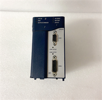
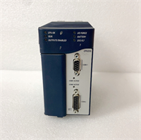
- Observe the LED indicators: PWR (Green), OK (Green), RUN (Green).
- The OK LED should turn solid green within 15-20 seconds. Flashing red indicates a fault or missing battery.
- Connect a laptop via USB or Ethernet. Open Proficy Machine Edition.
- Go online. Verify the hardware configuration matches the physical setup and check the firmware version.
Troubleshooting Quick Reference
| Symptom | Probability | Action |
|---|---|---|
| OK LED Flashing Red | High | Check battery voltage. Verify firmware compatibility with the project file. Reload firmware if corrupted. |
| No Ethernet Link | Medium | Check cable integrity and switch port lights. Verify IP address settings in the hardware configuration. |
| Battery Alarm (BAT LED) | High | Replace the CR2032 battery immediately while the unit is powered to retain RAM data. |
| Module Not Recognized | Low | Inspect backplane pins for bending or debris. Reseat the module firmly. |
| Slow Scan Time | Low | Check for excessive logic or infinite loops in the program. Optimize code structure. |
| Serial Comm Failure | Medium | Verify RS-232/485 setting in hardware config matches the wired device. Check pinout wiring. |
Dimensions, Mounting & Wiring Notes
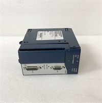
- Dimensions: Approx. 12.0 cm (H) × 10.0 cm (W) × 14.5 cm (D) – Standard RX3i single-slot width.
- Mounting: Slides into RX3i universal backplane. Uses integrated locking levers; no screws needed for mounting.
- Terminal Notes: Ethernet ports are standard RJ45. Serial port is a D-Sub 9-pin male (or terminal block depending on specific sub-revision, usually DB9 for CPU315).
- Warning: Do not hot-swap this CPU unless the system is explicitly configured for it (rare for standalone units). Always power down for safety.
IC695CPU315-CD GE
FAQ
Q: What is the difference between CPU315 and CPU320?
A: The CPU315 has a 64 MHz processor and 2 MB memory, while the CPU320 has a 1 GHz processor and 10 MB memory. The 320 is significantly faster and supports larger programs/I/O counts. Choose based on application complexity.Q: Does the “CD” suffix mean it has different ports?
A: No. The “CD” typically refers to a manufacturing revision or packaging configuration. The port layout (2 Ethernet, 1 Serial, 1 USB) remains standard for the CPU315 model.Q: Can I use this CPU for redundancy?
A: No. The IC695CPU315 is a standalone CPU. Redundancy requires specific redundant CPU models (e.g., CPU3xxR) and a redundancy kit.Q: What software is required to program this?
A: You need Proficy Machine Edition (PME). Older software like Logicmaster 90-30 is not compatible with the RX3i architecture.Q: How long does the battery last?
A: Typically 3 to 5 years under normal conditions. The “BAT” LED will illuminate when the voltage drops below a safe threshold, indicating immediate replacement is needed to prevent data loss during power cycles.Q: Is this compatible with 90-30 I/O modules?
A: No. The RX3i (IC695) uses a different backplane and connector than the 90-30 (IC693) series. You must use RX3i-specific I/O modules. Communication between the two systems is possible via Ethernet or Serial.
Quality Transparency Strategy (SOP)
1. Incoming Inspection
- Origin Verification: Validate serial number format against Emerson/GE production records.
- Suffix Check: Confirm “CD” revision label matches expected hardware build.
- Physical Inspection: Check Ethernet ports for bent pins, housing cracks, and backplane connector cleanliness.
- Battery Check: Measure internal battery voltage. Replace if < 3.0V DC.
2. Live Functional Testing
- Test Rack Setup: Installed in an RX3i backplane with dummy I/O modules.
- Boot Sequence: Verify successful boot and “OK” LED stability within 20 seconds.
- Memory Test: Write/Read test patterns across the full 2 MB memory space to verify integrity.
- Comm Stress Test: Run simultaneous Ethernet (SRTP/Modbus) and Serial traffic for 4 hours. Monitor for packet loss.
- Test Report: Document firmware version, battery voltage, and pass/fail status of all ports.
3. Electrical Testing
- Backplane Continuity: Verify continuity on all 96 pins.
- Port Integrity: Test Ethernet link negotiation (10/100 Mbps) and Serial loopback.
- Power Draw: Measure 5V current consumption to ensure it matches specs (~0.8A).
4. Firmware/Revision Verification
- Firmware Version: Document pre-loaded firmware. Update to latest stable version if requested.
- Configuration Backup: Save existing hardware config before wiping.
- Visual Record: High-res photos of the label showing “CPU315-CD” and serial number.
5. Final QC & Packaging
- QC Sign-off: Technician verifies all functional tests.
- ESD Protection: Sealed in anti-static bag with desiccant.
- Packaging: Double-boxed with foam inserts to protect connectors.
- Documentation: Include test report and battery installation date.
Technical Pitfall Guide
- Memory Limitations:
- Risk: Trying to load a massive program (>1.5 MB) onto the 2 MB CPU315.
- Result: Download fails or runtime performance degrades severely due to memory fragmentation.
- Fix: Estimate memory usage early. If >2 MB is needed, upgrade to CPU320 or CPU330.
- Battery Neglect:
- Scenario: Ignoring the “BAT” LED during routine checks.
- Consequence: Power flicker causes total program loss.
- Prevention: Replace batteries proactively every 3 years. Keep a backup of the program on a PC.
- Ethernet Switch Misconfiguration:
- Detail: The CPU has a built-in switch.
- Risk: Creating network loops by incorrectly wiring the two ports to the same switch without spanning tree protocol.
- Fix: Use one port for HMI/SCADA and the other for daisy-chaining remote I/O or drives, or configure VLANs if supported.
- Software Version Mismatch:
- Scenario: Using an old version of Proficy Machine Edition that doesn’t support the “CD” revision firmware.
- Result: Connection errors or inability to go online.
- Fix: Check the firmware version on the CPU label and ensure your PME software has the appropriate support packs installed.
- Backplane Pin Damage:
- Risk: Forcing the module into the slot.
- Consequence: Bent pins break communication lines.
- Protocol: If resistance is felt, stop immediately. Inspect alignment. Never force the levers.


