 Tel:
Tel:  Email:
  WhatsApp:
 Description
Key Technical Specifications
| Parameter | Value |
|---|---|
| Input Voltage | 24VDC Nominal (10–30VDC range) |
| Number of Points | 16 Inputs |
| Logic Type | Negative (Sinking) / Common Cathode |
| On-State Current | 2.5 mA typical @ 24VDC |
| Off-State Leakage | < 1.5 mA |
| Input Impedance | 3.3 kΩ typical |
| Response Time | 0.5 ms (On), 0.5 ms (Off) typical |
| Isolation | 1500VAC between field and logic bus |
| Grouping | 1 common per 8 points (2 groups) |
| Power Consumption | 70 mA @ 5VDC (backplane) |
| Operating Temp | 0°C to 60°C (32°F to 140°F) |
| Dimensions (HxWxD) | 12.7 x 3.5 x 10.2 cm (approx.) |
Product Introduction
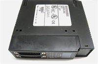
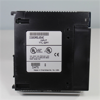
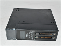
The IC693MDL654 provides 16 channels of 24VDC digital input capability for GE Series 90-30 PLC systems, specifically designed for sinking (negative logic) sensor interfaces. It converts field switch states into logic levels readable by the CPU with high noise immunity.This module features grouped commons, allowing two separate voltage references within a single card, which simplifies wiring for mixed-potential zones. The 0.5 ms response time ensures fast detection of high-speed limit switches without missing pulses. (Technicians appreciate the dual-LED status indicators per point, making fault finding visible without a laptop.)
Installation & Configuration Guide
Phase 1: Preparation (10 min)
- Verify rack power is OFF. Lockout/Tagout (LOTO) the main control panel breaker.
- Identify the target slot. Ensure it matches the I/O configuration table in the PLC program.
- Check the terminal block type. The MDL654 uses a removable 20-point terminal block (IC693ACC301 or similar).
- Inspect the module connector pins. Bent pins will prevent proper backplane communication.
Phase 2: Removal (5–10 min)
- If wired directly, label every wire according to the schematic before disconnecting.
- If using a terminal block, unplug the block from the module face. Do not pull wires out individually.
- Loosen the two captive mounting screws at the top and bottom of the module.
- Pull the module straight out. Support the weight to avoid stressing the backplane.
- Real-world detail: If the terminal block plastic looks melted or discolored near specific terminals, check for loose wire strands causing arcing before connecting the new unit.
Phase 3: Installation (10 min)
- Align the module guides with the rack rails. Slide in firmly until the backplane connector seats.
- You must feel a solid stop. No gap should exist between the module face and the rack chassis.
- Tighten mounting screws to 1.2 Nm. Loose modules vibrate loose over time, causing intermittent faults.
- Reconnect the terminal block or wire directly to the screw terminals.
- Torque terminal screws to 0.5–0.6 Nm. Ensure no bare copper is exposed outside the terminal clamp.
Phase 4: Power-On & Test (10 min)
- Apply 24VDC field power to the sensor commons first, then rack logic power.
- Observe the LEDs. With no inputs active, all green point LEDs should be OFF.
- Activate a known good sensor (e.g., close a limit switch). The corresponding LED must turn ON instantly.
- Verify the input status in the PLC programming software (Proficy Machine Edition).
- Toggle the input 5 times rapidly. Ensure the software status tracks the physical LED without lag.
Troubleshooting Quick Reference
| Symptom | Probability | Fastest Check | Action |
|---|---|---|---|
| All LEDs Off (Inputs Active) | High | Common Voltage | Measure 24VDC at the Common terminals. Check field fuse. |
| Specific Point Stuck On | Medium | Shorted Wire | Disconnect field wire. If LED stays on, module internal fault. If off, check field short. |
| Specific Point Stuck Off | Medium | Open Circuit | Measure voltage at terminal while activating sensor. Should read >10VDC. |
| Intermittent Flickering | High | Loose Terminal | Retorque all terminal screws. Check for frayed wire strands touching neighbors. |
| CPU I/O Fault Error | Low | Backplane Contact | Reseat the module. Clean backplane pins with contact cleaner if oxidized. |
| Wrong Logic State | Medium | Wiring Error | Verify wiring is Sinking (NPN). This module cannot source current for PNP sensors. |
Dimensions, Mounting & Wiring Notes
- Dimensions: 127 mm (H) x 35 mm (W) x 102 mm (D).
- Mounting: Inserts directly into Series 90-30 rack. Secured by two front-face screws.
- Terminal Notes: Uses 20-position terminal block. Points 1–8 share Common A; Points 9–16 share Common B.
- Wiring Logic: Requires NPN (sinking) sensors. The module provides the path to ground; the sensor supplies +24V.
- Grounding: Connect the rack grounding lug to earth ground using 14 AWG wire. Shielded cables should be grounded at one end only to prevent ground loops.
IC693MDL654 GE
FAQ
Q: Can I use this module with PNP (sourcing) sensors?
A: No. The IC693MDL654 is designed for negative logic (sinking) inputs only. Using PNP sensors will result in all inputs reading “ON” constantly. You would need the IC693MDL655 for PNP applications.Q: Why are half my lights on when nothing is connected?
A: This usually indicates a “ghost voltage” or induced voltage on the common wire. Check your common wiring; ensure Commons A and B are connected to the correct 24VDC return paths. (We often see users tie both commons to ground by mistake.)Q: What is the maximum wire size for the terminals?
A: The terminals accept 12 to 24 AWG solid or stranded copper wire. Use ferrules for stranded wire to prevent fraying under the screw clamp.Q: My PLC says “I/O Missing” for this slot. What do I check?
A: First, reseat the module firmly. Second, verify the slot number in the hardware configuration matches the physical slot. Third, check if the backplane pins are bent.Q: How do I know if the module is actually bad or just wired wrong?
A: Disconnect all field wires. Apply 24VDC directly to a point terminal and its corresponding common. If the LED doesn’t light, the module channel is dead. If it lights, your field wiring is the issue.Q: Is this compatible with the newer Emerson PACSystems?
A: No. This module is physically and electrically specific to the GE Series 90-30 architecture. It will not fit RX3i or RX7i racks.