 Tel:
Tel:  Email:
  WhatsApp:
 Description
Key Technical Specifications
| Parameter | Specification |
|---|---|
| Network Protocol | DeviceNet (ODVA Standard) |
| Role | Master / Scanner Only |
| Max Nodes | 64 (Node IDs 0-63) |
| Baud Rates | 125 kbps, 250 kbps, 500 kbps (Auto-detect or Configured) |
| Power Input | 24 VDC (External supply required for network power) |
| Backplane Power | 5 VDC (from 90-30 rack) |
| Data Mapping | Configurable Input/Output tables mapped to %I, %Q, %R, %AI, %AQ |
| Connection Types | Poll, Change-of-State (COS), Cyclic |
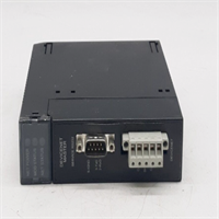
| Terminals | Removable 5-pin Phoenix Contact style (or integrated block) |
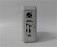
| Indicators | NET OK, NET FAULT, NODE STATUS, MS (Module Status), NS (Network Status) |
| Operating Temp | 0°C to 60°C (32°F to 140°F) |
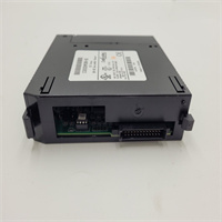
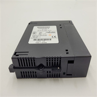
| Mounting | Single slot in 90-30 universal rack |
| Software Config | Proficy Machine Edition (Logic Developer – PLC) |
Product Introduction
The IC693DNM200-BD is the primary interface for connecting GE Fanuc 90-30 PLCs to DeviceNet networks. It acts as the Master scanner, polling connected slave devices (VFDs, motor starters, valve islands, remote I/O blocks) and exchanging data with the main CPU via the backplane.The “-BD” suffix indicates a specific hardware revision, often featuring updated components for better noise immunity or compatibility with newer firmware standards. This module eliminates the need for hard-wiring individual sensor signals to the PLC, significantly reducing wiring time and panel space. (Note: Proper termination and bias resistors on the DeviceNet trunk line are critical; missing these causes intermittent communication faults that are difficult to trace.)
Installation & Configuration Guide
Preparation (10 min)
Verify the DeviceNet network layout (trunk line and drop lines). Ensure you have a dedicated 24 VDC power supply for the DeviceNet network (separate from logic power if possible to reduce noise). Gather the EDS (Electronic Data Sheet) files for all slave devices you intend to connect. Install Proficy Machine Edition on your engineering laptop.
Removal (5–10 min)
Power down the PLC rack. Disconnect the DeviceNet cable from the green terminal block. If the block is removable, unplug it from the module. Release the locking tab on the faceplate. Slide the module out. Note the DIP switch settings (if used for baud rate) before removal, though modern config is software-based.
Installation (10 min)
Insert the IC693DNM200-BD into an available universal slot in the 90-30 rack. Lock the tab. Connect the external 24 VDC power to the module’s power terminals (if separate from the network port). Reconnect the DeviceNet cable ensuring correct polarity (Red = V+, Black = V-, White = Data+, Blue = Data-, Bare = Drain). Tighten terminal screws to 0.5 Nm.
Power-On & Test (10 min)
Apply power to the rack and the DeviceNet network. Observe the LEDs:
- MS (Module Status): Should be solid Green (Ready).
- NS (Network Status): Should flash Green (Online, no connection) then turn Solid Green (Connected) once the PLC runs and configures the scan list.
- NET FAULT: Must be OFF.
Connect via Proficy ME. Go online. Check the “DeviceNet Configuration” table. Verify that all expected nodes show “OK” status. Force a few outputs and monitor inputs to confirm data exchange.
Troubleshooting Quick Reference
| Symptom | Probability | Action |
|---|---|---|
| NS LED Red (Connection Fault) | High | Check baud rate mismatch between master and slaves. Verify node addresses (duplication?). |
| NS LED Flashing Red (Timeout) | Medium | A specific slave is not responding. Check power to that slave. Check cabling to that drop. |
| MS LED Red (Module Fault) | Medium | Hardware failure or corrupted configuration. Try downloading config again. Replace module if persistent. |
| Intermittent Data Loss | Medium | Check for missing termination resistors (121Ω) at both ends of the trunk. Check for ground loops. |
| PLC sees module but no I/O | Low | Verify the Scan List is enabled and the PLC is in RUN mode. The scanner only polls in RUN. |
Dimensions, Mounting & Wiring Notes
- Dimensions: Standard 90-30 single-slot width.
- Mounting: Any universal slot (not the power supply slot).
- Wiring Topology: Trunk-and-Drop. Do not daisy-chain devices in a line without a trunk. Max drop length depends on baud rate (e.g., at 500kbps, max drop is 6m).
- Termination: Requires 121Ω resistors at both physical ends of the trunk line. The module does not have internal termination switches; you must install external terminators.
- Power: The module needs 24VDC for its own logic (sometimes derived from backplane, check manual) AND the network needs 24VDC distributed on the red/black wires. Do not mix these supplies carelessly.
IC693DNM200-BD GE
FAQ
What does the “-BD” revision mean?
It signifies a hardware update over the original DNM200. It usually offers improved reliability and compatibility with later versions of Proficy Machine Edition. It is a direct replacement for earlier revisions (AA, AC, etc.).Can this module act as a DeviceNet Slave?
No. The IC693DNM200 is strictly a Master/Scanner. If you need the 90-30 PLC to appear as a slave to another master (like a Rockwell ControlLogix), you need a different module (e.g., a generic serial gateway or specific adapter), not the DNM200.Do I need to install EDS files?
Yes, for optimal configuration. While you can manually configure basic I/O sizes, importing the EDS file for each slave device (VFD, starter) automatically sets up the correct parameter mapping and connection types (Poll vs. COS).Why is my Network Status light flashing green?
Flashing Green means the module is online and powered, but the PLC CPU is not actively scanning the list (usually because the PLC is in STOP mode) or the configuration has not been downloaded/enabled. Put the PLC in RUN mode.How do I handle duplicate node addresses?
The scanner will fault (Red NS light) if two devices claim the same Node ID. You must physically change the rotary switches or DIP switches on the slave devices to ensure unique IDs (0-63).Can I use standard Ethernet cable for DeviceNet?
No. DeviceNet requires specific thick or thin coaxial-style cables (shielded twisted pair with drain) designed for the protocol’s electrical characteristics. Using Cat5/Cat6 will likely cause communication errors due to impedance mismatch.What is the maximum cable length?
Depends on baud rate:
- 125 kbps: 500 meters
- 250 kbps: 250 meters
- 500 kbps: 100 meters
Using repeaters can extend this distance.
Quality Transparency Strategy (SOP)
1. Incoming Inspection
Verify model number and “-BD” revision. Inspect the green terminal block for burnt pins (common if 24V was shorted). Check the DB9 or terminal port housing for cracks. Verify label legibility.2. Live Functional Testing
Install in a test 90-30 rack with a CPU. Connect a simulated DeviceNet network using a “DeviceNet Simulator” tool or actual slave devices (e.g., a small remote I/O block).
- Test at all three baud rates (125k, 250k, 500k).
- Configure a scan list with 10 simulated nodes.
- Run for 4 hours, toggling I/O bits rapidly.
- Monitor for “Connection Timeouts” in the diagnostic buffer. Zero timeouts allowed.
3. Electrical Testing
Check isolation between the backplane (5V) and the DeviceNet ports (24V/Signal). Verify continuity of the internal fuse (if accessible) or power input circuitry. Measure current draw on the 24V input; it should match spec (<150mA typically).4. Firmware Verification
Read the firmware version. Compare against the latest supported version for Proficy ME v8.0/v9.0. If the firmware is extremely old (pre-2005), we flag it as “Legacy” but do not upgrade unless requested, to avoid breaking old projects that rely on specific timing behaviors.5. Final QC & Packaging
Sign off on the baud rate stress test report. Pack with the removable terminal block (if detached during shipping) secured in a bag taped to the unit. Anti-static bag + bubble wrap. Label includes tested baud rates and firmware version.
Technical Pitfall Guide
Firmware Mismatch
Newer versions of Proficy Machine Edition may struggle to communicate with very old DNM200 firmware during the configuration download phase, even if runtime is fine. Solution: If connection fails during config, try an older version of the software or update the module firmware (requires special loader).DIP/Jumper Misconfiguration
While mostly software-configured, some early “-BD” units might have hardware switches for write-protect or boot mode. Ensure these are in the default “Run” position. Incorrect switch settings can prevent the module from accepting new configurations.Terminal Incompatibility / Wiring Errors
The most common failure: Reversed Polarity. Connecting Red to Black on the DeviceNet port can instantly destroy the transceiver chip. Always double-check wire colors against the pinout diagram before energizing. Also, forgetting the Drain Wire ground leads to massive noise issues.Power Supply Capacity Margin
The DeviceNet network power (red/black wires) must supply all slave devices. Users often underestimate the current needed for valves and drives on the network, causing voltage drops at the far end. This results in nodes dropping offline randomly. Calculate total slave current + margin.ESD Damage Risk
The DeviceNet transceiver is exposed on the external ports. Static discharge from unplugging cables in dry environments can fry the chip. Symptoms: Module powers up (Green MS) but never communicates (Red/Flash NS) even with a single known-good node. Always touch the chassis ground before handling cables.