
 Tel:
Tel:  Email:
  WhatsApp:
 Description
Key Technical Specifications
| Parameter | Specification |
|---|---|
| Bus Architecture | VME64x (P1 and P2 connectors) |
| Processor Interface | UCVE Main Processor Bridge |
| Redundancy Support | TMR (Triple Modular Redundancy) |
| Operating Voltage | +5V DC ± 5%, +3.3V DC auxiliary |
| Max Current Draw | 4.5A @ 5V DC (Typical load) |
| Temperature Range | -30°C to +65°C (-22°F to 149°F) |
| Humidity Tolerance | 5% to 95% Non-condensing |
| Communication Protocol | GE Global Data Memory (GDM) |
| Form Factor | Eurocard 6U VME |
| Firmware Base | Mark VIe Core Logic Rev 4.x+ |
| Weight | 0.85 kg (1.87 lbs) |
| MTBF | >100,000 hours (System dependent) |
Product Introduction
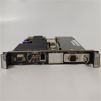
Most control room failures I’ve witnessed weren’t caused by code errors; they were physical layer breakdowns in the backplane comms. The GE IS215UCVEM09A sits right at that choke point. It’s the VME interface card for the Mark VIe UCVE processor pack. If this card glitches, your turbine trip logic goes blind, and you’re staring at a forced outage while management screams about lost MWs.Engineers keep this specific revision (09A) in their spare parts cage because it handles the VME bus arbitration without the timing drift seen in earlier 01-07 revisions. It sustains the 33 MHz transfer rate even when the cabinet temps hit 55°C in July, which is where cheaper clones fail. The Global Data Memory (GDM) exchange remains stable under high electrical noise. This specific revision is notoriously picky about grounding straps on the chassis, but otherwise bulletproof once seated correctly.
Quality SOP & Tech Pitfalls (The Reality Check)
The Lab Report (SOP)
Before we ship a unit, it goes through the gauntlet. First, a visual inspection under 10x magnification to check for counterfeit resoldering or bent VME pins. Then, it hits the test rack: we run a live loopback test simulating TMR voting for 4 hours. We check insulation resistance on the P1/P2 connectors using a Fluke 1587. Firmware version is logged and matched against the GE GFK-2359 manual. Finally, it’s bagged with anti-static foam and sealed. No exceptions.The Engineer’s Warning (Pitfalls)
Here is the disaster scenario: You swap this card without checking the DIP switch settings on the old failed unit. The IS215UCVEM09A uses specific hardware strapping for slot ID and termination. I once saw a plant down for 18 hours because a tech installed a fresh module with default factory switches. The UCVE processor couldn’t resolve the VME address, causing a “Loss of Comm” trip. Also, watch out for firmware mismatches. If your main UCVE CPU is running an older core logic, this 09A revision might timeout during the handshake. Verify the firmware load before you bolt the door shut.
Installation & Configuration Guide
Phase 1: Pre-Installation
⚠️ SHUT DOWN THE CONTROL POWER. Wait 30 seconds for capacitors to discharge. Take a high-res photo of the existing DIP switches and jumper positions on the failing card. Do not trust your memory; you will forget.Phase 2: Removal
Label every cable if disconnected (though usually, this is a backplane card). Release the DIN rail clips or ejector levers gently. If it sticks, do not pry with a screwdriver; you will damage the VME pins. Wiggle it straight out.Phase 3: Installation
Copy the DIP/Jumper settings from the old card to the new IS215UCVEM09A exactly. This step prevents 90% of startup failures. Align the card with the guide rails and seat it firmly until the ejector levers lock. Ensure the faceplate grounds properly to the chassis.Phase 4: Power-On & Testing
Restore 24V DC control power. Watch the LED sequence: Power OK should light green within 5 seconds. The “Comm” LED should flash rhythmically. Download the latest logic file via the HMI or Engineering Workstation. Verify there are no “VME Timeout” alarms in the diagnostic buffer.
IS215UCVEM09A GE
Compatible Replacement Models
| Compatibility Tier | Model Number | Notes |
|---|---|---|
| ✅ Drop-in Replacement | IS215UCVEM09A | Exact match. Ensure suffix matches. |
| ⚠️ Software Compatible | IS215UCVEM08A | Hardware identical, may require firmware downgrade or logic recompile. Estimate 2 hours labor. |
| ❌ Hardware Mod Required | IS215UCVEM01A | Obsolete revision. Pinout differs slightly. Do not use unless rewiring backplane (Not recommended). |
Frequently Asked Questions (FAQ)
Can I hot-swap this module while the turbine is running?
No. While Mark VIe supports some redundancy, the VME interface card is critical for inter-processor voting. Pulling it live will likely cause a loss of redundancy or a full system trip. Plan a shutdown window.My old card is revision 05A. Will the 09A work without changes?
Physically, yes. Logically, maybe not. The 09A has updated timing circuits. You must verify compatibility with your current Mark VIe software build. Check GE document GFK-2359. If the system complains about “Hardware Mismatch,” you’ll need to update the core logic.Does this come with the VME backplane connectors?
No. This is just the card. The P1/P2 connectors are soldered to your chassis backplane. If those pins are bent, fix the chassis first, or this new card won’t seat.What if the “Status” LED stays red after power-up?
9 times out of 10, it’s a DIP switch setting error or a bad ground connection. Double-check your photos of the old card. If that’s correct, the VME bus might be noisy—check your shielding.Is this unit refurbished or new?
We supply New Surplus. It’s original GE stock that was never installed, sitting in climate-controlled storage. It’s not a cleaned-up used card with reheated solder joints. You get the factory seal.


