
 Tel:
Tel:  Email:
  WhatsApp:
 Description
Key Technical Specifications
| Parameter | Specification |
|---|---|
| Processor | Intel Pentium M (Embedded Low-Power) |
| Clock Speed | 1.0 GHz |
| Memory (RAM) | 512 MB ECC SDRAM (Onboard) |
| Storage | 256 MB CompactFlash (User replaceable) or onboard Flash |
| Bus Interface | VME64x (32-bit data/address) |
| Network Ports | Dual 10/100 Base-TX Ethernet (RJ45) |
| Serial Ports | 2x RS-232 (Front access via ribbon or direct) |
| Operating Temp | -40°C to +70°C (Conduction cooled) |
| Watchdog | Hardware & Software configurable (Critical for Trip Logic) |
| Power Requirement | 5V DC @ 2.5A typical (12.5W) |
| Form Factor | 6U VME Eurocard |
Product Introduction
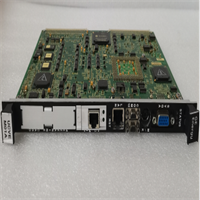
When your gas turbine is spinning at 3,600 RPM and the control network starts dropping packets, you don’t need a generic PC; you need the IS215UCVEM01A. This board was the workhorse that brought reliable Ethernet connectivity to the Mark VIe architecture without sacrificing the deterministic behavior required for trip logic. Unlike its predecessors that relied on external comm modules, this unit has dual Ethernet ports baked right into the faceplate, cutting down cabling clutter and potential failure points in the cabinet.Engineers specifically hunt for the “EM” revision because it handles the ToolboxST communication loads better than the older non-Ethernet UCVs, especially when archiving trend data to historians. It runs cool enough to survive in a cramped simplex rack where airflow is questionable, provided your fans are actually working. A word of caution: the RJ45 connectors on these older units can get brittle. I’ve seen techs snap a clip off just by plugging in a stiff patch cable, so treat the ports like glass.
Quality SOP & Tech Pitfalls (The Reality Check)
The Lab Report (SOP)
We don’t trust “plug-and-play” claims from surplus dealers. Here is our actual bench protocol:
- Visual & Counterfeit Check: We inspect the conformal coating for cracks (sign of thermal cycling) and verify the Intel chipset markings haven’t been sanded off.
- Live VME Test: The board is seated in a verified Mark VIe test rack. We run a continuous memory stress test for 12 hours to catch intermittent ECC errors.
- Port Verification: Using a laptop and a crossover cable, we ping both Ethernet ports simultaneously while flooding the VME backplane with I/O traffic. If packet loss exceeds 0.1%, the board fails.
- Firmware Audit: We boot into the BIOS and log the version. Many returned cores have corrupted bootloaders from improper shutdowns in the field. We reflash if needed to match current Toolset standards.
- Final Seal: Unit is cleaned, bagged with humidity indicators, and sealed in static-free packaging.
The Engineer’s Warning (Pitfalls)
The number one killer of these installations? IP Address Conflicts and Subnet Masks. The IS215UCVEM01A often ships with a factory default IP (like 192.168.1.10) that clashes with your plant’s existing scheme. If you plug it in without setting the DIP switches or using the serial console to pre-configure the IP, you can flood the network and knock offline other running controllers. I watched a refinery shut down a whole unit because a new spare card started broadcasting ARP requests with a duplicate IP. Also, never ignore the CompactFlash card health; if the CF card is old, the file system can corrupt during a sudden power loss, leaving the controller bricked until you swap the flash.
Installation & Configuration Guide
Time estimate: 30 minutes.
- Pre-Installation ⚠️
- Safety First: Place the controller in “Disable” mode via the HMI. Wait for the logic to stop scanning.
- Cut power to the specific VME rack. Wait 45 seconds for capacitors to discharge.
- CRITICAL: Photograph the DIP switch block and any jumpers on the failed card. Note the MAC address sticker if visible.
- Removal
- Label the Ethernet cables (Port A vs. Port B) and serial ribbons.
- Open the ejector levers fully. Wiggle gently to break the vacuum seal if stuck.
- Slide out the module carefully, avoiding contact with the VME pins.
- Installation
- MATCH THE SWITCHES: Set the DIP switches on the new IS215UCVEM01A exactly as per your photo. This defines the slot ID and boot mode.
- If replacing the CompactFlash, ensure the new card is pre-imaged with the correct firmware image.
- Seat the module firmly until the ejectors lock. Reconnect Ethernet and serial cables.
- Power-On & Testing
- Restore power. Observe the LED sequence: Power -> Boot -> Run.
- Connect via Serial Console first (using HyperTerminal or PuTTY) to verify the IP address before trying Ethernet.
- Launch ToolboxST. Download the project database. Verify “Online” status and check CPU load % (should be <40% idle).
GE IS215UCVEM01A
Compatible Replacement Models
| Compatibility Tier | Model Number | Notes |
|---|---|---|
| ✅ Drop-in Replacement | IS215UCVEM01A | Exact match. Ensure firmware revision is compatible with existing TMR peers. |
| ⚠️ Software Compatible | IS215UCVEM01B | Later revision. Hardware identical, but may require a BIOS flash to match older rack firmware. |
| ⚠️ Software Compatible | IS215UCVGM06A | Different processor architecture (Pentium III vs M). Requires logic recompilation and full system download. Not a hot-swap. |
| ❌ Hardware Mod Required | IS215UCVBM01A | Lacks integrated Ethernet. Requires adding a separate comm module and cabling changes. Avoid for direct swaps. |
Frequently Asked Questions (FAQ)
Q: Can I swap this card while the turbine is running?
A: No. The UCV is the brain. In a Simplex system, pulling it trips the machine. In a TMR (Triple Modular Redundant) system, you lose a voting leg. While the machine might stay up on the remaining two legs, you are flying blind with no redundancy. If one of the other legs fails while you are swapping this one, you get an immediate shutdown. Always plan a controlled outage.Q: The LEDs are flashing amber/green repeatedly. Is it broken?
A: Not necessarily. That pattern usually means it’s stuck in the bootloader or can’t find a valid image on the CompactFlash. Check your serial console output. Often, the CF card has corrupted, or the DIP switches are set to “Boot from Network” instead of “Boot from Flash.” Reset the switches to the correct position and cycle power.Q: Do I need to recompile my logic when swapping to a fresh IS215UCVEM01A?
A: If the hardware revision is identical (EM01A to EM01A), no. You just download the existing project file. However, if you are forced to use a newer revision (like EM01B) or a different CPU type, you must open the project in ToolboxST, verify the hardware definition, recompile, and then download. Never assume binary compatibility across different CPU generations.Q: How do I know if the CompactFlash card is bad?
A: If the board powers up, the LEDs do their self-test, but then hang on a specific pattern (often solid amber or rapid flashing) and you get “Read Error” or “File System Corrupt” on the serial console, the CF is dead. These industrial cards have a limited write cycle life. Keep a spare, pre-imaged CF card in your spares kit; it’s cheaper than waiting for a whole new board.Q: Why does the serial port not connect even though the COM settings are right?
A: Check the ribbon cable pinout. GE used some proprietary pinouts on the front panel headers for these VME cards. If you are using a standard off-the-shelf serial adapter, it might be crossed wrong. Use the OEM-specific cable or verify the pinout against the Mark VIe Hardware Manual (GEH-6721). Also, ensure no other process is holding the COM port open on your laptop.


