 Tel:
Tel:  Email:
  WhatsApp:
 Description
Key Technical Specifications
- Input Channels: 16 Independent Differential Inputs
- Sensor Types: J, K, E, T, R, S, B, N, C (Software selectable per channel)
- Resolution: 24-bit Sigma-Delta ADC
- Input Impedance: >10 MΩ
- Common Mode Rejection: >100 dB at 50/60 Hz
- Cold Junction Compensation: Automatic per channel (±0.5°C accuracy)
- Isolation Voltage: 1500 V DC channel-to-backplane
- Scan Rate: Configurable (Typical 10ms – 100ms per channel group)
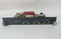
- Backplane Interface: 6U VMEbus (J1/J2 connectors)
- Operating Temperature: -30°C to +65°C (-22°F to +149°F)
- Power Consumption: 1.5 A @ 5V DC (Approx.)
- LED Diagnostics: Channel Fault, Module Run, Comm Status
Product Introduction
Nothing kills a turbine startup faster than a noisy temperature reading, and that’s exactly where the GE IS215ACLEH1BB earns its keep. I’ve pulled these out of racks vibrating so hard the screws were walking loose, only to find the card still holding steady while cheaper clones would have drifted into a false trip. This isn’t just a generic analog card; it’s the gatekeeper for your exhaust thermocouples. If this board lies about the temperature, the controller thinks the turbine is melting when it’s ice cold, or vice versa. It handles the dirty work of filtering out electrical noise from nearby generators and converting microvolts into reliable engineering units.The reason seasoned engineers specify the ‘B’ revision of the H1 model is simple: stability. Early versions struggled with cold junction compensation drift when cabinet temps swung wildly between night and day. This version locks that down, keeping accuracy within ±0.5°C even when the control room HVAC is fighting a losing battle. It supports every thermocouple type you’ll throw at it, from Type K for general monitoring to Type R for high-temp zones. Just a heads-up: the terminal block connections on these can be finicky if you don’t torque them to spec; loose wires here mean erratic spikes that will drive you crazy trying to diagnose.
Quality SOP & Tech Pitfalls (The Reality Check)
The Lab Report (SOP)
We don’t trust “plug and play” with analog cards. Every IS215ACLEH1BB gets a full signal injection test. We hook up a Fluke 725 calibrator and simulate all supported thermocouple types across the full temperature range (-50°C to 1200°C). We check linearity at 10% intervals and verify cold junction compensation by heating the card itself in an environmental chamber while monitoring a static input. Visual inspection focuses heavily on the isolation barriers; any carbon tracking or burnt spots on the PCB means immediate rejection. We also verify the firmware checksum against the GE library to ensure the linearization tables haven’t been corrupted. Finally, it goes into a static-shield bag with humidity indicators.
The Engineer’s Warning (Pitfalls)
The biggest headache I’ve seen with this card isn’t the hardware; it’s the configuration mismatch. You install a fresh IS215ACLEH1BB, but the ToolboxST project file still has the old channel types defined (e.g., expecting Type J on Channel 3 when you wired a Type K). The card reads it, but the value is garbage, leading to immediate combustion trouble alarms. Another disaster zone is grounding. These inputs are floating, but if you ground the shield at the field sensor AND the cabinet, you create a ground loop that injects 60Hz noise right into your temperature readings. I once spent six hours chasing a “faulty sensor” ghost only to find a double-grounded shield. Cut the shield at the field end, ground it only at the cabinet. Always.
Installation & Configuration Guide
- Pre-Installation
- ⚠️ Safety First: Ensure the turbine control system is in a safe state. If possible, disable combustion monitoring loops to prevent false trips during the swap.
- ⚠️ ESD Protection: Wear a grounded wrist strap. Analog front-ends are incredibly sensitive to static discharge.
- Document Wiring: Take a clear photo of the existing terminal block wiring. Label every wire with its channel number (CH1-CH16).
- Removal
- Disconnect the terminal block plug from the front of the card (do not pull individual wires if a plug is used).
- Release the ejector levers at the top and bottom of the card.
- Slide the card out smoothly. Inspect the backplane connector for bent pins or debris.
- Installation
- Verify Jumpers/Switches: Some revisions have hardware switches for filter settings; ensure they match the old card or the system manual.
- Seat the new IS215ACLEH1BB firmly into the slot until the ejectors lock.
- Reconnect the terminal block plug. Double-check polarity on every single channel. One reversed wire ruins the average temperature calculation.
- Power-On & Testing
- Power up the rack. Watch the LED sequence; “RUN” should go solid green.
- Open ToolboxST online. Monitor the raw channel values. They should read ambient temperature (or open circuit if disconnected).
- Inject a known millivolt signal or use a heat gun on a spare sensor to verify the reading changes correctly and matches the expected curve.
- Check for “Open Thermocouple” alarms on unused channels; terminate unused inputs properly to avoid noise coupling.
IS215ACLEH1BB GE
Compatible Replacement Models
| Model Number | Compatibility Tier | Notes |
|---|---|---|
| IS215ACLEH1BA | ⚠️ Software Compatible | Earlier ‘A’ revision. Hardware fits, but may require firmware update for improved cold junction accuracy. |
| IS215ACLEH1BC | ✅ Drop-in Replacement | Newer ‘C’ revision. Direct swap. Improved noise filtering algorithms in firmware. Recommended upgrade. |
| IS215ACLEM08A | ❌ Hardware Mod Required | Different channel count (8-channel vs 16-channel) and pinout. Requires rewiring and chassis slot reconfiguration. |
Frequently Asked Questions (FAQ)
Can I replace just one bad channel instead of the whole card?
No. The analog front-end circuitry is integrated onto the main PCB. If one channel is fried due to a surge, the isolation on the others is likely compromised too, even if they read okay today. Replace the entire IS215ACLEH1BB module. It’s cheaper than chasing intermittent faults later.Why are my temperature readings fluctuating wildly after installation?
Check your shielding first. If you haven’t grounded the cable shield at exactly one point (usually the cabinet end), you’re picking up electromagnetic interference from the generator or exciter. Also, verify that the “Cold Junction Compensation” feature is enabled in the software config; without it, room temperature changes will look like process changes.Is this card compatible with Mark V systems?
Absolutely not. Mark V uses a completely different bus architecture and physical form factor (often terminal boards mounted separately). Trying to force this VME-based card into a Mark V system will damage the backplane. This is strictly for Mark VIe and VIe+ architectures.How do I handle unused channels?
Don’t leave them floating. Floating inputs act like antennas and suck in noise, which can bleed into adjacent active channels through the multiplexer. Short the positive and negative terminals of unused channels together and connect them to the local analog ground, or configure them as “disabled” in the ToolboxST project if the firmware allows.What if the card fails the “Open Thermocouple” diagnostic immediately?
First, check the wiring continuity from the terminal block to the sensor. If the wiring is good, verify the channel configuration in ToolboxST matches the actual sensor type installed. If you have a Type K sensor but the software expects Type J, the resistance check might fail or read out of range. If config and wiring are perfect, the card’s internal fuse or input protection diode might be blown—swap the card.